Hummer H1 (2002+). Manual — part 286
_____________________________________________________
PCM/Tech 1 Scan Tool 77
®
05745159
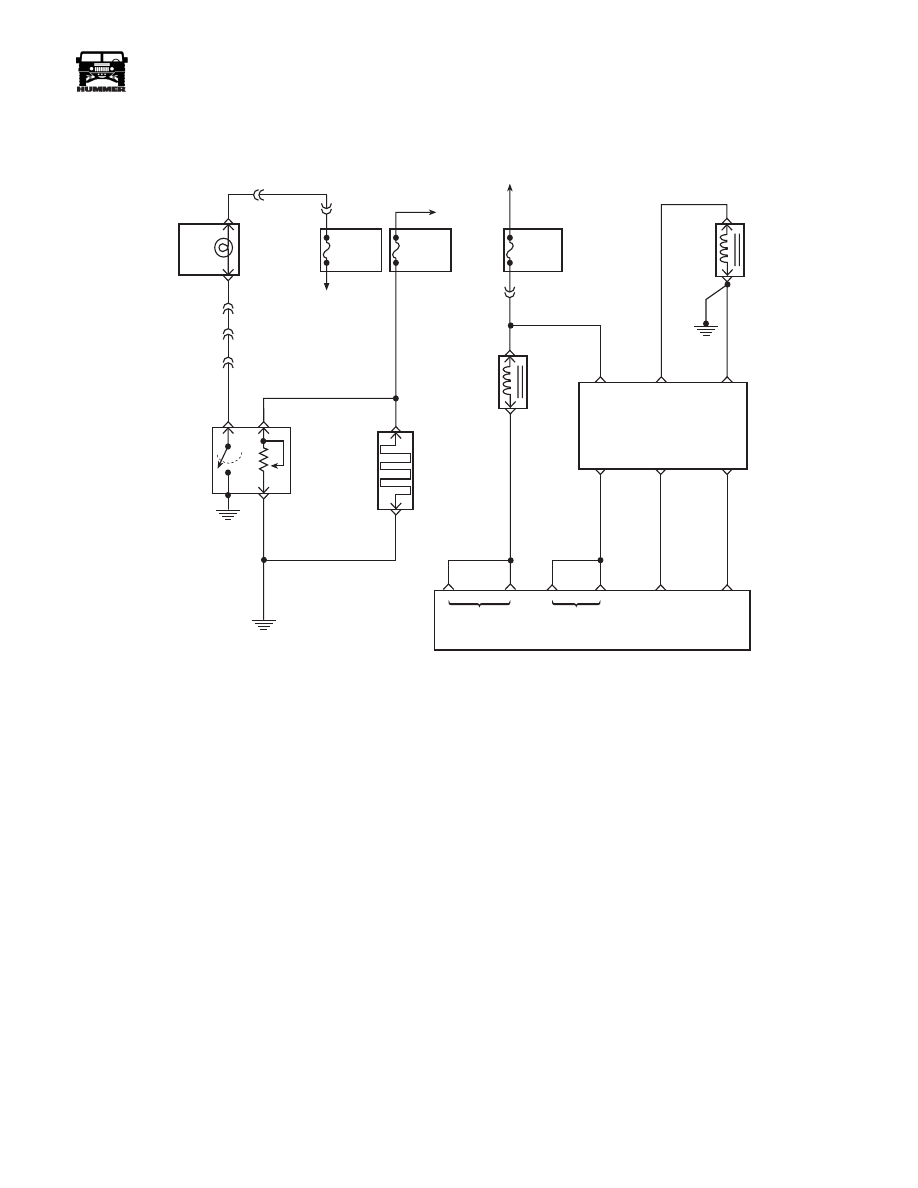
DTC P0263, P0266, P0269, P0272, P0275,
P0278, P0281 and P0284 Cylinder Balance
System Faults
Circuit Description
The PCM has the ability to increase and decrease the amount
of fuel to each cylinder to provide smooth idle operation. If the
fuel correction exceeds define limits, DTC P0263 will set. This
is a type D DTC.
Conditions for Setting the DTC
• Engine at idle.
• Engine coolant at normal temperatures.
• Cylinder fault must be constant.
• Fuel correction amount exceeds limits (internal to
PCM).
• Conditions met for 2 seconds.
Action Taken When the DTC Sets
Possible rough idle.
Conditions for Clearing the MIL/DTC
• A History DTC will clear when forty consecutive
warm-up cycles that the diagnostic does not fail (coolant
temperature has risen 5°C (40°F) from start up coolant
temperature and engine coolant temperature exceeds
71°C (160°F) that same ignition cycle).
• Use of a Scan Tool.
Diagnostic Aids
Injector balance test on scan tool should be used to confirm
faulty cylinder. Scan tool will cutout specific cylinder re-
quested. If original complaint was multiple cylinder balance
DTCs and vehicle has a manual transmission, dual mass fly-
wheel could be at fault. It’s possible that if a cylinder balance
fault has been detected and engine has been running for a long
time, the PCM will try to increase or decrease fuel in other cyl-
inders to compensate for a rough idle which will cause multiple
cylinder balance DTCs to set. The scan tool snap shot mode
can be used to properly identify the suspected cylinder. The
most likely cause of cylinder balance DTCs are faulty nozzles
or engine mechanical (low compression) problems.
Test Description
Number(s) below refer to the number(s) on the diagnostic ta-
ble.
2. This step will properly identify a suspected cylinder by
looking for a RPM drop (if RPM drops, cylinder is contrib-
uting, if not, cylinder is not contributing).
FUSE 3B
20AMP
EXTERIOR
FUSE BOX
DRAIN
FILTER
HOT IN RUN
AND START
WATER IN
FUEL LIGHT
LEFT HAND
STATUS CENTER
C9-D
C3-F4
C1-45
B
A
327 YL
C
C9-J
WATER IN
FUEL
SENSOR
FUEL
HEATER
291 PK
57 BK
G2
57 BK
C
A
9-S12-056
FUSE 4B
5AMP
INTERIOR
FUSE BOX
TO
IGNITION
SWITCH
C3-N7
30 GY
FUSE 3A
20AMP
EXTERIOR
FUSE BOX
HOT IN RUN
AND START
C5-A4
239 PK
ENGINE
SHUTOFF
SOLENOID
FUEL
SOLENOID
701 DB
A
A
A
B
C
D
F
E
A
B
FUEL
SOLENOID
DRIVER
IGN
FUEL
SOLENOID
HIGH
FUEL
SOLENOID
LOW
FUEL
SOLENOID
CONTROL
CLOSURE
SIGNAL
CLOSURE
GROUND
ESO
SOLENOID
CONTROL
FUEL INJECT
CONTROL
CLOSURE
SIGNAL
CLOSURE
GROUND
712 LG
713 RD
491 BK
POWER
CONTROL
MODULE
C28-C15
C28-D3
C28-C3
C27-C13
C29-A1

78
PCM/Tech 1 Scan Tool
_____________________________________________________
®
DTC P0263, P0266, P0269, P0272, P0275, P0278, P0281 and P0284
Cylinder Balance System Faults
Step
Action
Value(s)
Yes
No
1
Important:
Before clearing DTC(s) use the scan tool “Capture Info” to
record freeze frame and failure records for reference, as data will be lost
when “Clear Info” function is used.
Was the
“On-Board Diagnostic (OBD) System Check”
performed?
—
Go to Step 2.
Go to
OBD
System Check.
2
1. Scan tool connected.
2. Start and idle engine.
3. Engine at operating temperature.
4. Make sure all DTCs are cleared.
5. Using the scan tool, cutout (“Inj. Balance”) the suspected cylinder.
Is there an RPM drop in the suspected cylinder?
—
Go to Step 3. Go to Step 4.
3
DTC is intermittent. If no additional DTCs are stored, refer to “Diagnostic
Aids”. If additional DTCs are stored, refer to those table(s).
Are additional DTCs stored?
—
Go to the
applicable
DTC table.
Go to
Diagnostic
Aids.
4
Check for a basic engine mechanical or fuel delivery problem in that cylin-
der.
Was a repair performed?
—
Go to Step 6.
Go to Step 5.
5
Replace the fuel injection pump. Refer to
Fuel Injection Pump
.
Is the action complete?
—
Go to Step 6.
—
6
1. Using the Scan Tool, select “DTC”, “Clear Info”.
2. Start engine and idle at normal operating temperature.
3. Select “DTC”, “Specific”, then enter the DTC number which was set.
4. Operate vehicle within the conditions for setting this DTC as specified in
the supporting text.
Does the Scan Tool indicate that this diagnostic Ran and Passed?
—
Go to Step 7.
Go to Step 2.
7
Using the Scan Tool, select “Capture Info”, “Review Info”.
Are any DTCs displayed that have not been diagnosed?
—
Go to the
applicable
DTC table
System OK.
_____________________________________________________
PCM/Tech 1 Scan Tool 79
®
05745159
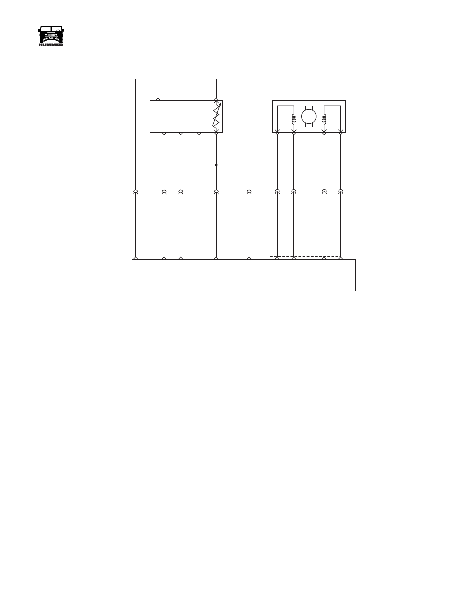
DTC P0335 Crankshaft Position (CKP) Sensor
Circuit Performance
Circuit Description
The crankshaft position sensor is a “Hall-effect” type sensor
that monitors crankshaft position and speed. There are four
teeth 90 degrees apart on the front of the crankshaft sprocket
that induce a pulse in the sensor which is transmitted to the
PCM. There is a physical one to one correspondence between
the pump cam and crankshaft. This is a type A DTC.
Conditions for Setting the DTC
• RPM less than 300.
• 8 consecutive cam pulses missing for 8 #1 cylinder
events.
or
• RPM greater than or equal to 300.
• 8 consecutive cam pulses missing for 32 #1 cylinder
events.
Action Taken When the DTC Sets
Backup fuel.
Conditions for Clearing the MIL/DTC
• The PCM will turn the MIL off after three consecutive
trips without a fault condition.
• A History DTC will clear when forty consecutive
warm-up cycles that the diagnostic does not fail (coolant
temperature has risen 5°C (40°F) from start up coolant
temperature and engine coolant temperature exceeds
71°C (160°F) that same ignition cycle).
• Use of a Scan Tool.
Diagnostic Aids
When PCM is in backup fuel, long crank times, fast idle and
poor performance conditions will exist. Check for good con-
nection at crankshaft position sensor and at PCM. Many inter-
mittent problems are caused by faulty electrical connections or
wiring. When attempting to diagnose an intermittent problem,
always begin by trying to reproduce the conditions under
which the failure occurs. This usually involves raising the en-
gine to a higher temperature or operating it near RPM that the
problem occurs. Since heat and vibration are often the cause of
intermittent, this may bring out the failure.
Test Description
Number(s) below refer to the number(s) on the diagnostic ta-
ble.
2. This step will determine if DTC P0335 is the result of a hard
failure or an intermittent condition.
4. This step checks the 5 volt reference circuit (the 5 volt refer-
ence may vary slightly).
5. This step checks the ground circuit.
A
E
B
F
D
C
5 VOLT
REFERENCE
OPTICAL/ FUEL
TEMP SENSOR
PUMP CAM
SENSOR
SIGNAL
HIGH
RESOLUTION
SIGNAL
SENSOR
GROUND
M
D
A
B
C
C5
C3
B8
C1
C12
C2
375 GY
442 BR
703 OR
156 PK
225 YL
C27-D14
C29-A4
C29-A2
C27-D9
C27-C8
FUEL TEMP
SIGNAL
SENSOR
GROUND
HIGH
RES
SIGNAL
CAM
SENSOR
SIGNAL
5 VOLT
REFERENCE
INJECTION TIMING
STEPPEN MOTOR (ITS)
A3
A2
A6
A7
709 RD
708 TN
710 OR
71
1 YL
C29
A8
A9
A10
A7
ITS
HI
ITS
LO
ITS
LO
ITS
HI
POWERTRAIN
CONTROL
MODULE
9-S12-070

80
PCM/Tech 1 Scan Tool
_____________________________________________________
®
DTC P0335 - Crankshaft Position Sensor Circuit Performance
Step
Action
Value(s)
Yes
No
1
Important:
Before clearing DTC(s) use the scan tool “Capture Info”.
Was the
“On-Board Diagnostic (OBD) System Check”
performed?
—
Go to
Step 2.
Go to
OBD
System
Check.
2
Start and idle engine.
With throttle closed, observe “Crank Ref. Missed” display on scan tool. Does
scan tool display specified value?
8
Go to
Step 4.
Go to
Step 3.
3
DTC is intermittent. If no additional DTCs are stored, refer to “Diagnostic
Aids”. If additional DTCs are stored, refer those table(s).
Are additional DTCs stored?
—
Go to the
applicable
DTC table.
Go to
Diagnostic
Aids.
4
Ignition “OFF”.
Disconnect the Optical/Fuel temperature sensor electrical connector.
Ignition “ON" engine “OFF”.
Using a DVM (J–39200), measure voltage between the Optical/Fuel tempera-
ture 5 volt reference circuit and chassis ground.
Is voltage at specified value?
4.8 - 5.2v
Go to
Step 5.
Go to
Step 7.
5
Probe sensor ground circuit with test light connected to B+. Is test light “ON”?
—
Go to
Step 6.
Go to
Step 8.
6
Reconnect the Optical/Fuel temperature sensor.
Back probe the Optical/Fuel temperature sensor signal circuit at the PCM with a
DVM (J–39200) connected to ground.
Crank engine.
Is voltage at the specified value?
4v
Go to
Step 11.
Go to
Step 10.
7
Ignition “OFF”.
Disconnect PCM and check Optical/Fuel Temp. 5 volt reference circuit for
open, short to ground, or short to sensor ground circuit.
If the Optical/Fuel temperature 5 volt reference circuit is open or shorted to
ground, repair as necessary.
Was the circuit open or shorted to ground?
—
Go to
Step 14.
Go to
Step 9.
8
Check for open or poor sensor ground terminal conn. at PCM.
If a problem is found, repair it. Was a repair performed?
—
Go to
Step 14.
Go to
Step 13.
9
Check the Optical/Fuel temperature 5 volt reference circuit for a poor connec-
tion at PCM and replace terminal if necessary.
Did the terminal require replacement?
—
Go to
Step 14.
Go to
Step 13.
10
Ignition “OFF”.
Disconnect PCM and check Optical/Fuel temperature signal circuit for open,
short to ground, or short to sensor ground circuit.
If the Optical/Fuel temperature signal circuit is open or shorted to ground, re-
pair it. Was the Optical/Fuel temperature signal circuit open or shorted to
ground?
—
Go to
Step 14.
Go to
Step 11.
11
Check the Optical/Fuel temperature signal circuit for a poor connection at the
PCM and replace terminal if necessary.
Did the terminal require replacement?
—
Go to Step
14.
Go to Step
12.
12
Replace the Crankshaft position sensor. After replacing the sensor, the PCM
must be programmed with a new TDC OFFset
. Refer to the Service Manual for
more information on the Crankshaft Position Sensor or reprogramming the
PCM.
Is the action complete?
—
Go to Step
14.
—
13
Replace the faulty PCM.
Notice:
If the PCM is faulty, the new PCM must be
programmed. Is the action complete?
—
Go to Step
14.
—
Нет комментариевНе стесняйтесь поделиться с нами вашим ценным мнением.
Текст