Hummer H1 (2002+). Manual — part 287

_____________________________________________________
PCM/Tech 1 Scan Tool 81
®
05745159
14
Using the Scan Tool, select “DTC”, “Clear Info”.
Start engine and idle at normal operating temperature.
Select “DTC”, “Specific”, then enter the DTC number which was set.
Operate vehicle within the conditions for setting this DTC.
Does the Scan Tool indicate that this diagnostic Ran and Passed?
—
Go to Step
15.
Go to Step
2.
15
Using the Scan Tool, select “Capture Info”, “Review Info”.
Are any DTCs displayed that have not been diagnosed?
—
Go to the
DTC table
System OK.
DTC P0335 - Crankshaft Position Sensor Circuit Performance
Step
Action
Value(s)
Yes
No
82
PCM/Tech 1 Scan Tool
_____________________________________________________
®
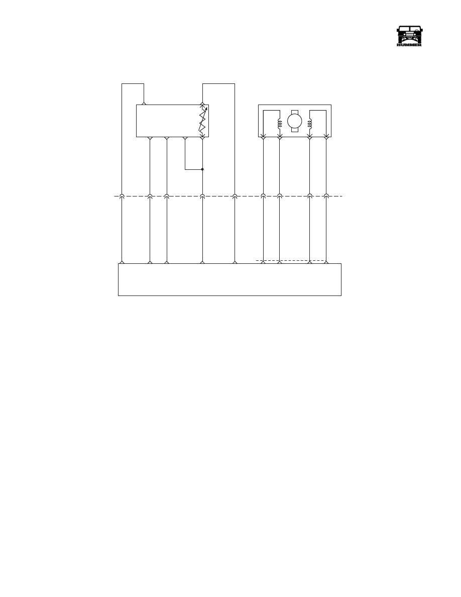
DTC P0370 Timing Reference High
Resolution
Circuit Description
The optical sensor provides a high resolution signal to the
PCM by counting pulses on the sensor disk located in the injec-
tion pump. The high resolution is one of the most important in-
puts by the PCM for fuel control and timing. This test monitors
the number of high resolution pulses which have been missed
(not detected). It’s based on a comparison between the number
of pulses that were detected since the last pump cam pulse and
the number of the pulses that should have occurred. This is a
type A DTC.
Conditions for Setting the DTC
A number of High Resolution pulses (internal to PCM) per ev-
ery 8 cam reference pulses.
Action Taken When the DTC Sets
Backup fuel.
Conditions for Clearing the MIL/DTC
• The PCM will turn the MIL off after three consecutive
trips without a fault condition.
• A History DTC will clear when forty consecutive
warm-up cycles that the diagnostic does not fail (coolant
temperature has risen 5°C (40°F) from start up coolant
temperature and engine coolant temperature exceeds
71°C (160°F) that same ignition cycle).
• Use of a Scan Tool.
Diagnostic Aids
When PCM is in backup fuel, fast idle and poor performance
problems will exist. If P0251 is also stored, the snap shot mode
on the scan tool should be used to properly identify fault. It is
possible P0370 may set if there is air in fuel system (vehicle
running out of fuel).
Test Description
Number(s) below refer to the number(s) on the diagnostic ta-
ble.
2. This step will determine if there is a 5 volt reference.
3. This step checks the ground circuit.
4. This step will check to see if the sensor is sending a signal
back to the PCM.
A
E
B
F
D
C
5 VOLT
REFERENCE
OPTICAL/ FUEL
TEMP SENSOR
PUMP CAM
SENSOR
SIGNAL
HIGH
RESOLUTION
SIGNAL
SENSOR
GROUND
M
D
A
B
C
C5
C3
B8
C1
C12
C2
375 GY
442 BR
703 OR
156 PK
225 YL
C27-D14
C29-A4
C29-A2
C27-D9
C27-C8
FUEL TEMP
SIGNAL
SENSOR
GROUND
HIGH
RES
SIGNAL
CAM
SENSOR
SIGNAL
5 VOLT
REFERENCE
INJECTION TIMING
STEPPEN MOTOR (ITS)
A3
A2
A6
A7
709 RD
708 TN
710 OR
71
1 YL
C29
A8
A9
A10
A7
ITS
HI
ITS
LO
ITS
LO
ITS
HI
POWERTRAIN
CONTROL
MODULE
9-S12-070

_____________________________________________________
PCM/Tech 1 Scan Tool 83
®
05745159
DTC P0370 - Timing Reference High Resolution
Step
Action
Value(s)
Yes
No
1
Important:
Before clearing DTC(s) use the scan tool “Capture Info”.
Was the “On-Board Diagnostic (OBD) System Check” performed?
—
Go to Step 2.
Go to OBD
System Check.
2
1. Ignition “OFF”.
2. Disconnect the Optical/Fuel temperature sensor electrical connector.
3. Ignition “ON” engine “OFF”.
4. Using a J–39200, measure voltage between the Optical/Fuel temperature
5 volt reference circuit and chassis ground at harness connector.
Is voltage at the specified value?
.24 v
Go to Step 3.
Go to Step 5.
3
1.
Verify the optical sensor is disconnected.
2. Probe the sensor ground circuit with a test light connected to B+ at the
harness connector.
Is the test light ON?
Go to Step 4.
Go to Step 7
4
1.
Reconnect the Optical/Fuel temperature sensor.
2. Start the engine
3. Allow the engine to idle at the normal operating temperature.
4. Use a Scan Tool in order to command a 900 RPM idle.
5. With J39200 On the Hertz (Hz) scale, back probe a high resolution signal
circuit at the PCM.
Is the Hertz reading at the specified value?
3840 Hz (+/
-100)
Go to Step10
Go to Step 9
5
1.
Remove the electrical harness filter from the vehicle.
2. Check the resistance on the electical harness filter 5 volt reference circuit
(terminal A)
Is the resistance greater than the specified value?
2.0
Ω
go to step 13
go to step 6
6
1.
Turn the ignition off.
2. Remove the electrical harness filter from the vehicle.
3. Disconnect the PCM.
4. Check the Optical/Fuel temperature 5 volts reference circuit for and
open, short to ground, or short to the sensor ground circuit.
5. If the Optical/Fuel temperature 5 volt reference circuit is open or shorted
to ground, repair as necessary.
Was the Optical/Fuel temperature 5 volt reference circuit open or shorted to
ground?
—
Go to Step 14.
Go to Step 8.
7
1.
Check for and open or a poor sensor ground terminal connection at the
PCM.
2. If a problem is fournd, repair as necessary.
Was a repair performed?
—
Go to Step 14. Go to Step 12.
8
Check the Opitical/Fuel temperature 5 volt reference circuit for a poor con-
nection at the PCM and replace the terminal if necessary.
Did the terminal require replacement?
—
Go to Step 14. Go to Step 14.

84
PCM/Tech 1 Scan Tool
_____________________________________________________
®
9
1.
Turn the ignition OFF.
2. Disconnect the PCM.
3. Check the high resolution signal circuit for and open, short ot ground, or
short to the sensor ground circuit.
4. If the high resolutin signal circuit is open or shorted to ground, repair as
necessary.
5. Was the high resolution signal circuit open or shorted to ground?
—
Go to Step 14. Go to Step 11.
10
Check the high resolution signal circuit for a poor connection at the PCM
and replace terminal if necessary.
Did the terminal require replacement?
—
Go to Step 14. Go to Step 12.
11
Replace the injection pump.
Important: If injection pump is malfunctioning, the new injection pump
must be timed.
Is the action complete?
—
Go to Step 14.
—
12
Replace the PCM.
Important: The new PCM must be programmed.
Is the action complete?
—
Go to Step 14.
—
13
Replace the electrical harness filter.
Is the action complete?
—
Go to Step 14.
—
14
1. Using the Scan Tool, select “DTC”, “Clear Info”.
2. Start engine and idle at normal operating temperature.
3. Select “DTC”, “Specific”, then enter the DTC number which was set.
4. Operate vehicle within the conditions for setting this DTC.
Does the Scan Tool indicate that this diagnostic Ran and Passed?
—
Go to Step 15.
Go to Step 2.
15
Using the Scan Tool, select “Capture Info”, “Review Info”.
Are any DTCs displayed that have not been diagnosed?
—
Go to the
DTC table
System OK.
DTC P0370 - Timing Reference High Resolution
Step
Action
Value(s)
Yes
No
Нет комментариевНе стесняйтесь поделиться с нами вашим ценным мнением.
Текст