Hummer H1 (2002+). Manual — part 152

________________________________________
Axles, Suspension, and Frame 9-69
®
05745159
Straightening
1.
When performing straightening repairs with the frame on
the vehicle:
• Use spreader plates or wood blocking to distribute chain
force to avoid damage to frame box section.
• Be sure to loosen sufficient length of frame to allow
frame force points to move without causing other dam-
age.
• Restrain vehicle movement in both directions along line
of force application.
2.
Vertical bends, except at end sections, require removal of
frame rail from vehicle.
3.
Application of bulk heating to frame components is not
authorized, metal properties will be irreversibly degraded.
4.
At the conclusion of a bend repair, carefully inspect welds
in the vicinity of repair and area of force application. Any
evidence of cracking or chipping of welds must be
repaired.
Figure 9-157: Frame Dimensions
MEASURE FROM CENTER
OF BODY MOUNT
BRACKET HOLES
72.304-72.124
INCHES
49.150-48.850
INCHES
77.026-76.466
INCHES
29.30-29.06
INCHES
MEASURE FROM OUTSIDE
EDGE OF FRAME RAILS
MEASURE FROM CENTER
OF BODY MOUNT
BRACKET HOLES

9-70
Axles, Suspension, and Frame
_________________________________________
®
WINCH (OPTION) PRIOR TO VIN 186477
Winch Troubleshooting
Winch Inoperative
1.
Check for jammed winch cable.
2.
Check winch control cable connector for corrosion or
loose connection. Clean corroded connector or secure
loose connection.
3.
Check for loose or damaged winch power cables. Using
voltmeter, connect positive meter lead to positive power
cable (red) at the winch motor, and negative meter lead to
the winch motor ground cables (black). If voltage is not
present, repair or replace winch power cables.
4.
Disconnect winch control from winch. Using an
ohmmeter, check for continuity between the common
terminal and the other two terminals on winch control
cable connector. Check for continuity one at a time, while
holding control in the OUT position and IN position. If
continuity is present in both positions, repair winch. If
continuity is not present in both positions, replace winch
control.
Winch Replacement
Removal
WARNING: To avoid personal injury or damage, sup-
port winch during removal.
1.
Disconnect battery ground cables (Section 12).
2.
Remove two battery cable bolts, battery cables, and winch
cables from battery (Figure 9-158).
Figure 9-158: Winch Cables On Battery
3.
Remove nut, lockwasher, capscrew, and clamp from right
frame extension. Discard lockwasher. Pull winch cables
through the splash shield to front of vehicle
(Figure 9-159).
Figure 9-159: Frame Bracket
4.
Remove four nuts, washers, bolts, and winch from front
bumper (Figure 9-160).
Figure 9-160: Winch and Winch Cables
POSITIVE
BATTERY
NEGATIVE
POSITIVE
BATTERY CABLE
BATTERY
CABLE
WINCH
CABLE
NEGATIVE
WINCH CABLE
BATTERY CABLE
BOLTS
CLAMP
FRAME BRACKET
POWER CABLES
CLAMP
POSITIVE
CONTROL
NEGATIVE
FRONT BUMPER
WINCH
NUT
BOX
COVER
WINCH
CABLE
WINCH
CABLE
________________________________________
Axles, Suspension, and Frame 9-71
®
05745159
5.
Remove two bolts and clamps securing winch cables to
winch.
6.
Remove three bolts and control box cover from winch.
NOTE:
It may be necessary to remove plastic coating com-
pound from winch in order to perform steps 7 and 8.
7.
Remove capscrew, washer, and negative winch cable from
winch.
8.
Remove locknut and positive winch cable from winch.
Discard locknut.
Installation
NOTE:
Positive winch cable must be positioned to align with
the opening in the control box cover.
1.
Install positive winch cable on winch with locknut
(Figure 9-160).
2.
Install negative winch cable on winch with washer and
capscrew.
3.
Coat motor end of winch with coating compound.
4.
Install control box cover on winch with three bolts.
5.
Secure two winch cables to winch with two clamps and
bolts.
6.
Install winch on front bumper with four washers, bolts,
and nuts. Tighten bolts to 60 lb-ft (81 N•m).
7.
Route winch power cables through the splash shield.
8.
Install winch cables on frame bracket with clamp,
capscrew, lockwasher, and nut (Figure 9-159).
9.
Connect battery ground cables (Section 12).
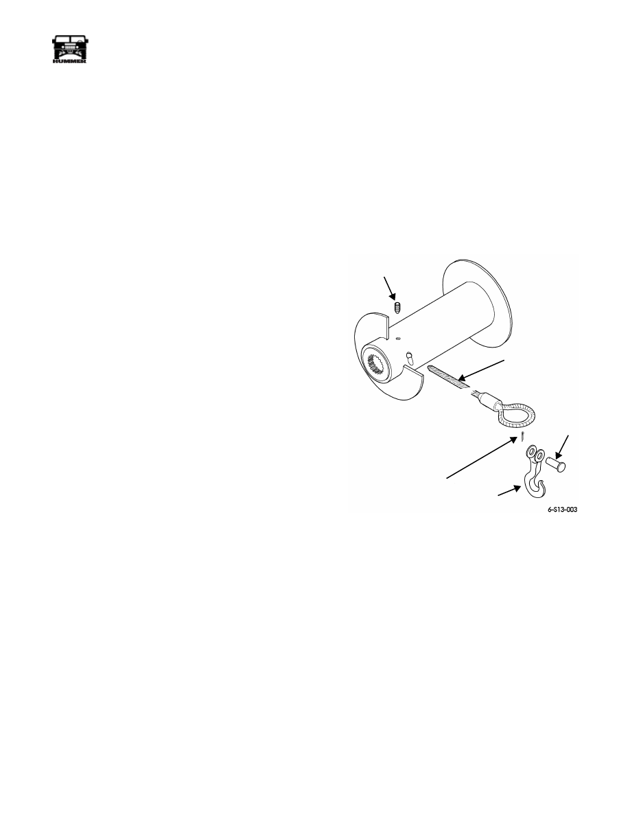
Winch Cable Replacement
WARNING: To avoid injury, wear gloves when han-
dling winch cable.
Removal
1.
Unwind winch cable.
2.
Remove set screw and winch cable from drum assembly
(Figure 9-161).
3.
Remove cotter pin, clevis pin and hook from winch cable.
Discard cotter pin.
Figure 9-161: Winch Cable
Installation
1.
Install hook, clevis pin and cotter pin on winch cable.
2.
Install winch cable on drum assembly with set screw.
CAUTION: Install winch cable on drum under a load of at
least 500 lb (227 kg), or outer wraps will draw into
inner wraps and damage cable.
NOTE:
Spool winch cable according to rotation label on
winch or brake will not function.
3.
Rewind and lubricate winch cable.
SET SCREW
COTTER PIN
HOOK
ROPE ANCHOR
WIRE ROPE
ASSEMBLY
CLEVIS
PIN

9-72
Axles, Suspension, and Frame
_________________________________________
®
Winch Assembly Repair
Disassembly
1.
Remove winch and winch cable.
NOTE:
Tag leads for assembly.
NOTE:
It may be necessary to remove plastic coating from
winch in order to perform steps 2 through 5.
2.
Remove three nuts and control leads from motor
(Figure 9-162).
Figure 9-162: Control Leads
3.
Loosen clamp and remove control from motor
(Figure 9-163).
Figure 9-163: Control Unit
4.
Remove clamps from motor.
5.
Mark motor end drum support, gear train assembly, and
gear end drum support for assembly (Figure 9-164).
Figure 9-164: Drum Support and
Gear Train Assembly
6.
Remove six bolts, three tie rods, motor end and gear end
drum supports from winch.
7.
Remove motor, and motor end drum support from drum
assembly.
8.
Remove motor brake driver and spacer from motor shaft.
9.
Remove drum assembly from gear train assembly
(Figure 9-164).
10. Remove two nylon thrust washers from drum
(Figure 9-165).
Figure 9-165: Thrust Washers and Brake
LEAD
CONTROL
CLAMP
DRUM SUPPORT
NUT
MOTOR
CONTROL
CLAMP
MOTOR
MOTOR
(SHOWN WITHOUT CONTROL)
SPACER (2)
DRUM SUPPORT
BRAKE
BRAKE
DRUM
ASSEMBLY
DRIVER
MOTOR END
DRUM SUPPORT
MOTOR END
TIE ROD
GEAR TRAIN
ASSEMBLY
NYLON THRUST
WASHER
BRAKE
DRUM
NYLON THRUST
WASHER
SET SCREW
BRAKE RETENTION
NOT REMOVABLE
BEARING
TOLERANCE
RING
ASSEMBLY
Нет комментариевНе стесняйтесь поделиться с нами вашим ценным мнением.
Текст