Hummer H1 (2002+). Manual — part 151
________________________________________
Axles, Suspension, and Frame 9-65
®
05745159
VERTICAL (SIDE VIEW) MEASUREMENT
1.
Select a hard and level surface area 1-1/2 times the size of
the vehicle.
2.
Raise vehicle at four points until all four wheels are off the
surface.
WARNING: When using shim material with jack-
stands, the shim material must be placed squarely and
firmly under the jackstand. The vehicle could be
knocked off the jackstand resulting in personal injury
or equipment damage if shim material is placed on top
of jackstand.
3.
Measure the distance from the floor to the bottom of the
frame near each jackstand. Place shim(s) under jackstands
as necessary until the floor-to-frame distances are equal at
each jackstand.
NOTE:
Measurements must be taken at identical locations on
the left and right frame rails. Failure to do so will result in a
faulty indication.
4.
Select, measure and record the distance from the floor to
the frame rail at several different points on either frame
rail.
5.
Measure and record frame rail height at corresponding
points on opposite frame rail.
6.
Compare measurements from both frame rails.
Measurements from comparable points deviating more
than 1/8-inch (3 mm) for each 2 feet of linear distance
indicates a vertically bent frame.
7.
Lower vehicle from jackstands.
HORIZONTAL (BOWING) MEASUREMENT
1.
Position vehicle on a smooth level surface.
2.
Measure height of frame rails at each end near center of
crossmembers. If heights vary by more than 1/8-5/16-inch
(3-8 mm), raise frame rail and install jackstands to bring
frame to level.
WARNING: When using shim material with jack-
stands, the shim material must be placed squarely and
firmly under the jackstand. The vehicle could be
knocked off the jackstand resulting in personal injury
damage if shim material is placed on top of jackstand.
3.
Hang a plumb bob at the corner of one frame rail where
the frame rail intersects the crossmember. Tape a piece of
paper to the floor under plumb bob and mark location
where plumb bob stops moving. Repeat procedure for
each corner of the frame (Figure 9-154).
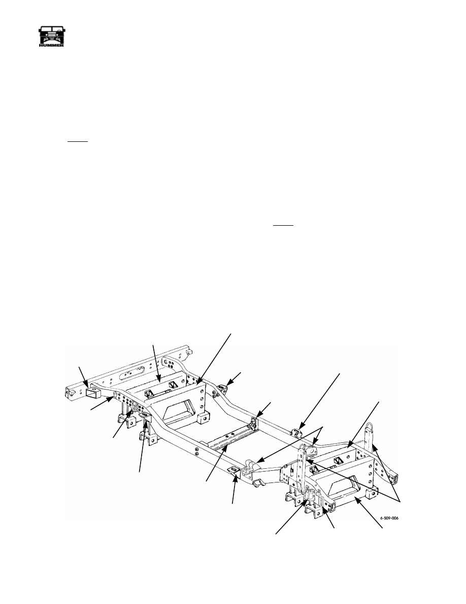
Figure 9-152: Frame Components
REAR SUSPENSION
REAR CROSSMEMBER
REAR SUSPENSION
FRONT CROSSMEMBER
LEFT
INTERMEDIATE
BODY MOUNT
BRACKET
REAR BUMPER
OUTER MOUNTING
BRACKET
RIGHT
REAR-REAR
TIEDOWN
BRACKET
RIGHT
REAR-FRONT
TIEDOWN
BRACKET
RIGHT INTERMEDIATE
BODY MOUNT
BRACKET
TRANSMISSION
CROSSMEMBER
RIGHT FRONT
BODY MOUNT
BRACKET
RIGHT FRONT
SPRING SEAT
RIGHT SPLASH
SHIELD BRACKET
AIR LIFT
BRACKETS
LEFT
TRANSMISSION
CROSSMEMBER
SUPPORT
BRACKET
LEFT FRONT
BODY MOUNT
BRACKET
ENGINE
MOUNT
BRACKET
FRONT
SUSPENSION
REAR
CROSSMEMBER
FRONT
SUSPENSION
FRONT
CROSSMEMBER
9-66
Axles, Suspension, and Frame
_________________________________________
®
NOTE:
Strings used for this horizontal bow measurement will
remain in place until the next measurement (Frame Skew) is
completed. To maintain the integrity of the measurements, the
string must be pulled tight and secured.
4.
Stretch string tightly on floor between front and rear
plumb bob marks under each frame rail (Figure 9-154).
5.
Measure front and rear crossmembers to determine center
point. Drop a plumb bob from crossmember center points
to the floor. Mark location where plumb bob stops moving
(Figure 9-154).
6.
Stretch a string tightly on floor between front and rear
plumb bob marks under crossmembers to determine
centerline (Figure 9-154).
7.
Select measuring points an equal distance apart along the
right and left strings. Measure from these right and left
points to the center string. Mark center string. The
distance from the right and left points to the center string
should be within 1/4-inch (6 mm) of being equal. If
measurements are not equal, one frame rail is bowed.
DIAGONAL (SKEW MEASUREMENT)
METHOD 1
1.
Measure diagonally from one point on right or left frame
rail string to a point on opposite frame rail string
(Figure 9-153).
2.
Compare to an opposite diagonal measurement.
3.
If the two measurements differ by more than 1/4-inch
(6 mm), the frame rails are skewed.
4.
Repeat this procedure at four other sets of measure points
to confirm the skew.
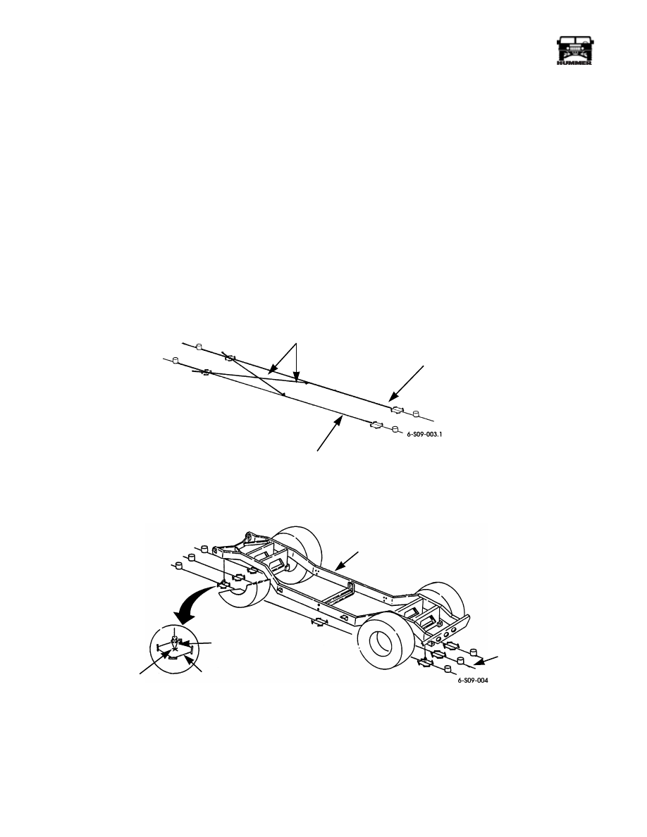
Figure 9-153: Diagonal Skew Measurement Method I
Figure 9-154: Horizontal (Bowing) Measurement
LEFT SIDE STRING
RIGHT SIDE STRING
DIAGONAL MEASUREMENTS
SHOULD NOT DIFFER BY MORE
THAN 1/4-INCH (6 MM)
LEFT FRAME RAIL
CENTERLINE STRING
PLUMB BOB
PAPER
MARK LOCATION
________________________________________
Axles, Suspension, and Frame 9-67
®
05745159
METHOD 2
1.
Position a string across a plumb bob point on each of the
frame rail strings (Figure 9-155).
2.
Place a square with one leg coincident with a frame rail
string (Figure 9-155).
3.
Run a line or string along other leg of square to opposite
frame rail string (Figure 9-155).
4.
Measure deviation between string positioned in Step 1 and
square leg line or string. Any deviation means the two
frame rails are skewed and, consequently, the
crossmembers are not at square angles to the frame rails. A
deviation of 1/2-inch (12.7 mm) makes a vehicle “dog
track” and it is difficult to align the wheels.
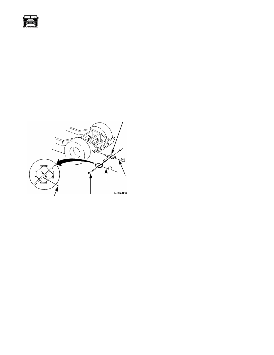
Figure 9-155: Diagonal Skew Measurement
Method 2
FRAME REPAIRS
Cracks
NOTE:
All frame welding should be heli-arc type.
1.
Cracks not extending across two adjacent faces of the
frame rail may be welded.
• Stop-drill crack with 1/8-inch (3 mm) drill
(Figure 9-156)
• Vee-notch crack (Figure 9-156)
• Heli-arc weld crack with Mig or Tig welder (using a
filler metal in accordance with AWS A5.18)
(Figure 9-156)
• If reinforcement or fishplate is to be added, grind weld
to a flat surface (Figure 9-156)
• A reinforcement or fishplate should be added to a frame
rail with a crack in the bottom face
• Longitudinal welding can be performed on any frame
rail face
2.
Welded reinforcements or fishplates should not be less
than 6-inches (15.2 cm) in length along frame rail.
3.
Bolt on reinforcements or fishplates should not be less
than 8-inches (20.3 mm) in length. The long bottom edge
of fishplate should be heli-arc lap welded to frame
component.
4.
Puncture holes only in side faces of frame rails may be
repaired with combinations of fishplates and/or
reinforcements. Welded type should only be used.
Puncture holes in bottom face are not repairable and
therefore the frame rail should be replaced.
5.
Bolted-on repairs should use grade 8 bolts with hardened
washers and nuts. Use proper torque when tightening nuts.
SQUARE
RIGHT SIDE
STRING
LINE OR STRING
FROM LEG OF
SQUARE
LEFT SIDE
STRING
DEVIATION LIMIT
1/2-INCH (12.5 MM)
9-68
Axles, Suspension, and Frame
_________________________________________
®
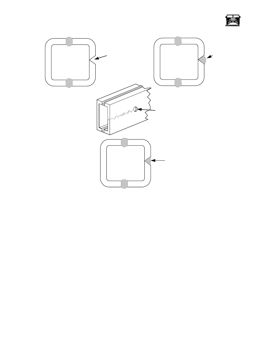
Figure 9-156: Crack Repair
Bends
1.
Do not attempt to repair a bend when:
• Buckling to a height of 1/4-inch (6 mm) on any one face
of the frame rail is involved.
• The bending also includes more than minor twisting.
• The frame rail is bent in two directions.
• The bending involves a collapse of one or more faces of
the frame rail at a suspension or body attachment point.
6-S09-007
V-NOTCH
CRACK
HELI-ARC
WELD CRACK
STOP DRILL WITH
1/8-INCH (3MM)
DRILL
GRIND WELD FLAT
IF ADDING A
REINFORCEMENT
Нет комментариевНе стесняйтесь поделиться с нами вашим ценным мнением.
Текст