Hummer H1 (2002+). Manual — part 153
________________________________________
Axles, Suspension, and Frame 9-73
®
05745159
11. Loosen set screw that retains brake.
12. Push brake through open end of drum and remove
(Figure 9-165).
13. Remove driveshaft from gear train assembly
(Figure 9-166).
14. Turn gear train assembly over with gear end drum support
down. Remove ten hex-head screws and gear housing
from gear end drum support.
15. Remove gasket from gear end drum support. Discard
gasket (Figure 9-166).
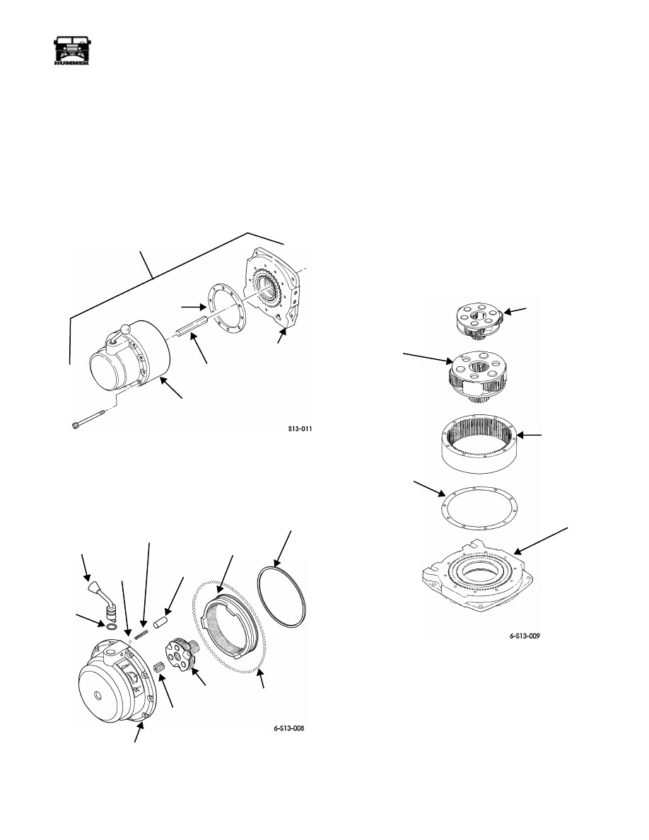
Figure 9-166: Gear Train Assembly
16. Remove detent spacer, spring, and detent ball from gear
housing (Figure 9-167).
Figure 9-167: Gear Housing
17. Remove clutch lever and O-ring seal from gear housing.
Discard O-ring seal.
18. Remove two retaining rings from gear housing
(Figure 9-167).
NOTE:
Intermediate ring gear comes out with 85 to 87 steel
balls. Be sure to catch all 85 to 87 steel balls.
19. Remove intermediate ring gear and 85 to 87 steel balls
from gear housing.
20. Remove input gear carrier assembly from gear housing
(Figure 9-167).
21. Remove intermediate gear carrier and output gear carrier
from output ring gear and gear end drum support
(Figure 9-168)
.
Figure 9-168: Gear Carriers
22. Remove output ring gear and gasket from gear end drum
support.
Cleaning
CAUTION: To avoid damage to equipment, do not clean brake
assembly. Clean and inspect all winch components. Replace
defective parts.
GEAR TRAIN ASSEMBLY
GASKET
GEAR HOUSING
DRIVESHAFT
GEAR END
DRUM SUPPORT
O-RING
CLUTCH
LEVER
DETENT
BALL
SPRING
DETENT
SPACER
STEEL BALLS
GEAR
RETAINING
RINGS
CLUTCH
RING
GEAR
SUN
INPUT
CARRIER
GEAR
HOUSING
INTERMEDIATE
GEAR CARRIER
OUTPUT GEAR
CARRIER
OUTPUT
RING GEAR
GASKET
GEAR END
DRUM SUPPORT
9-74
Axles, Suspension, and Frame
_________________________________________
®
Inspection
1.
Inspect drum for damage to splined end flanges and tube
(Figure 9-169). Replace winch if damaged.
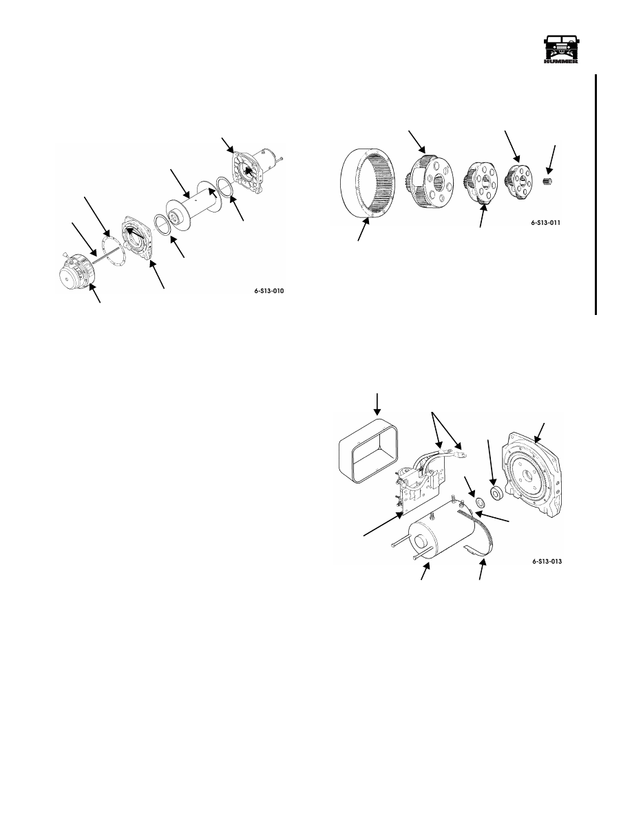
Figure 9-169: Drum Assembly and Gear Housing
Assembly
2.
Inspect gear end and motor end drum supports for damage.
Replace if damaged.
3.
Inspect gear housing for damage. Replace if damaged.
4.
Inspect thrust plate for damage or wear. Replace if
damaged or worn. Apply grease on thrust plate for
assembly.
5.
Inspect clutch lever and driveshaft for damage. Replace if
damaged.
6.
Inspect gear teeth and machined surfaces of intermediate
ring gear for damage. Replace if damaged.
7.
Inspect gear teeth, splines, and machined surfaces of
output ring gear, output gear carrier, intermediate gear
carrier, and input gear carrier assembly for damage.
Replace any damaged parts (Figure 9-170).
Figure 9-170: Gear Carriers
8.
Inspect brake assembly for damage (Figure 9-171).
9.
Inspect motor, spline, mating surface, and terminals for
damage. Replace motor if damaged (Figure 9-171).
Figure 9-171: Motor and Control Unit
10. Inspect cover for damage. Replace if damaged.
11. Inspect control for damaged leads, breaks in plastic
coating, and damaged mounting base. Replace control if
damaged or repair plastic coating.
MOTOR END
DRUM SUPPORT
DRUM
GEAR END
DRUM SUPPORT
DRIVE
SHAFT
GEAR
HOUSING
GASKET
THRUST
WASHER
THRUST
WASHER
OUTPUT
RING GEAR
OUTPUT
GEAR CARRIER
INTERMEDIATE
GEAR CARRIER
INPUT
GEAR CARRIER
ASSEMBLY
ASSEMBLY
(THIRD STAGE)
ASSEMBLY
(SECOND STAGE)
(FIRST STAGE)
SUN
GEAR
COVER
LEADS
CONTROL
SPLINE
MOTOR
DRUM
SUPPORT
BALL
BEARING
SPACER
CLAMP
3-1-01
________________________________________
Axles, Suspension, and Frame 9-75
®
05745159
Assembly
1.
Position 85 to 87 steel balls in groove of intermediate ring
gear and install intermediate ring gear in gear housing
(Figure 9-172).
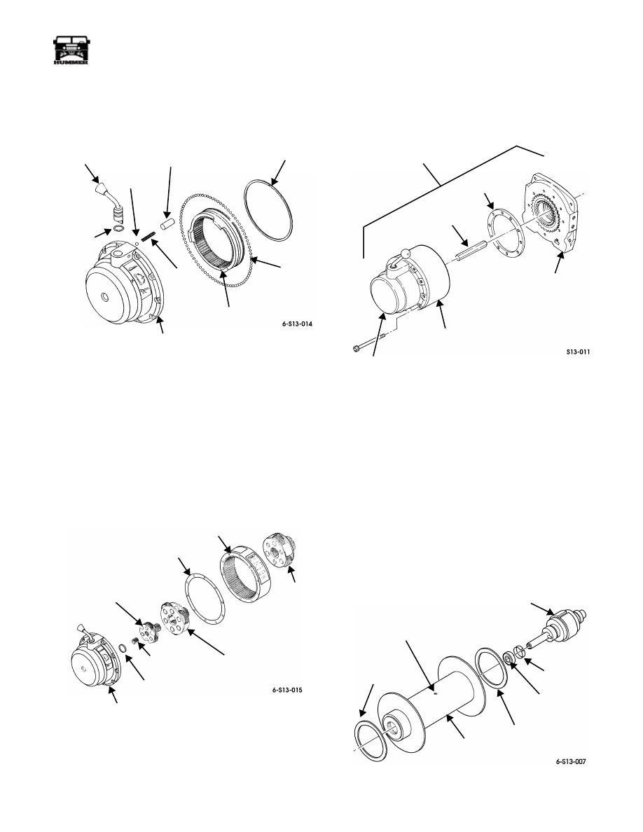
Figure 9-172: Intermediate Ring Gear and
Gear Housing
2.
Install retaining rings in gear housing.
3.
Apply light oil to steel balls through the clutch lever hole.
4.
Apply grease to clutch lever hole and install O-ring seal
and clutch lever in gear housing.
5.
Install detent ball, spring, and detent spacer in gear
housing.
6.
Apply aircraft grease to output gear carrier, intermediate
gear carrier, and input gear carrier assembly (Figure 9-173).
Figure 9-173: Gear Carriers
7.
Install input gear carrier assembly in gear housing.
NOTE:
Be sure ring gear engages in gear housing.
8.
Install gasket and output ring gear on gear housing.
9.
Install intermediate gear carrier on gear housing.
10. Install output gear carrier on intermediate gear carrier.
11. Install gasket on output ring gear (Figure 9-174).
Figure 9-174: Gear Train Assembly
NOTE:
Ensure spline on drum support engages in output ring
gear.
12. Install gear end drum support on output ring gear and gear
housing.
13. Secure gear housing assembly to drum support with ten
hex-head screws. Tighten hex-head screws to 100 lb-in.
(11 N•m).
14. Turn gear train assembly over with drum support facing
up.
15. Install driveshaft in gear train assembly (Figure 9-174).
16. Apply grease to drum bushings, seals, and output spline
(Figure 9-175).
Figure 9-175: Thrust Washers and Brakes
O- RING
CLUTCH
LEVER
DETENT
BALL
SPRING
DETENT
SPACER
CLUTCH
RING GEAR
RETAINING
RING
STEEL
BALLS
GEAR
HOUSING
SEAL
OUTPUT
GEAR
OUTPUT
RING GEAR
INTERMEDIATE
GEAR CARRIER
GASKET
INPUT
GEAR CARRIER
ASSEMBLY
GEAR
HOUSING
THRUST
WASHER
SUN
GEAR
CARRIER
GEAR TRAIN
ASSEMBLY
GASKET
DRIVE
SHAFT
GEAR END
DRUM SUPPORT
OUTPUT
RING GEAR
GEAR
HOUSING
NYLON THRUST
WASHER
BRAKE
DRUM
NYLON THRUST
WASHER
SET SCREW
BRAKE RETENSION
NOT REMOVABLE
BEARING
TOLERANCE
RING
ASSEMBLY

9-76
Axles, Suspension, and Frame
_________________________________________
®
17. With drum horizontal, install brake into drum.
18. Tighten brake retaining set screw to 18-22 ft-lb (24-30
N•m) torque.
19. Install two nylon thrust washers on drum.
20. Install drum assembly on gear train assembly. Rotate drum
assembly as needed to engage driveshaft, brake, and
output spline (Figure 9-176).
Figure 9-176: Drum Assembly and Gear
Train Assembly
21. Install brake drive and spacer to motor shaft.
22. Install motor end drum support on drum assembly.
23. Install motor on motor end drum support, ensuring to
engage brake drive with brake shaft end.
24. Install three tie rods between drum supports and secure
with six bolts. Tighten bolts to 18 lb-ft (24 N•m).
NOTE:
If motor or control have been pre-coated with sealing
compound, remove compound from between motor case and
control mounting gear contact area. Failure to do so may cause
improper grounding of control.
Figure 9-177: Control Unit and Motor
25. Connect three control leads to terminals and secure with
nuts (Figure 9-178).
26. Secure control to motor with clamp.
27. Re-coat motor end of winch (including all leads and
terminals) with PlastiDip Coating or equivalent
waterproofing compound.
28. Install winch assembly and winch cable.
Winch Electric Thermal Switch/Brush
Assembly Replacement
Removal
1.
Remove winch and winch cable.
NOTE:
Tag leads for assembly.
NOTE:
It may be necessary to remove plastic coating from
winch in order to perform steps 2 through 5.
2.
Remove three nuts and control leads from motor
(Figure 9-178).
3.
Loosen clamp and remove control from motor
(Figure 9-179).
MOTOR, 12 VDC
SHOWN WITHOUT CONTROL
SPACER (2)
DRUM SUPPORT
BRAKE
BRAKE
DRUM
ASSEMBLY
DRIVER
MOTOR END
DRUM SUPPORT
MOTOR END
TIE ROD
GEAR TRAIN
ASSEMBLY
CONTROL
CLAMP
MOTOR
Нет комментариевНе стесняйтесь поделиться с нами вашим ценным мнением.
Текст