Hummer H1 (2002+). Manual — part 132

_________________________________________________________
Steering System 8-35
®
05745159
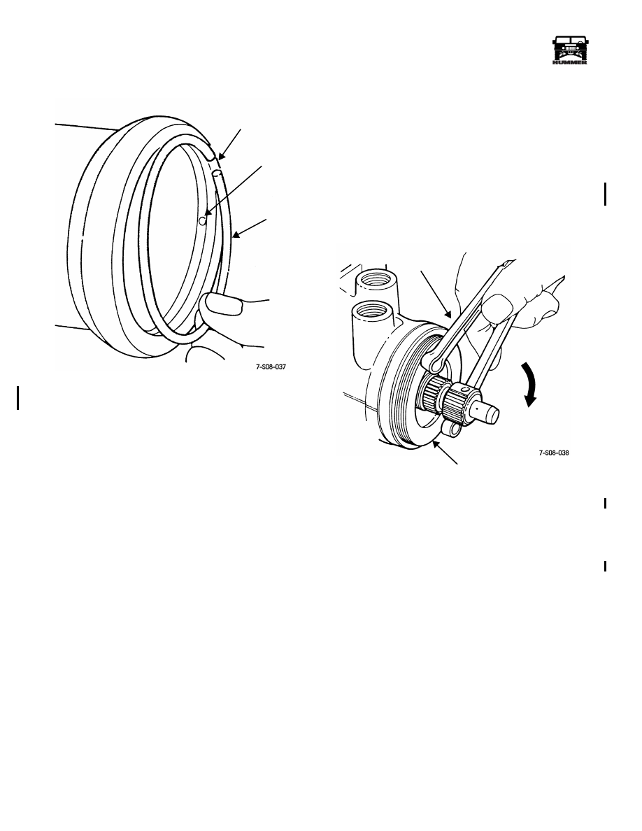
Figure 8-62: Adjuster Plug Assembly Sequence
Figure 8-63: Seating Adjuster Plug Retainer
Gear Housing Assembly
1.
Lubricate wormshaft, stub shaft-valve body, rack piston,
and adjuster plug with power steering fluid.
2.
Install wormshaft and stub shaft/valve body assembly in
gear housing. Be sure wormshaft thrust bearings are not
displaced during installation.
3.
Install adjuster plug in gear housing. Tighten plug only
enough to secure it in housing (2-3 threads).
4.
Install rack piston as follows:
a.
Place socket and ratchet on stub shaft.
b.
Insert rack piston into housing until wormshaft
contacts arbor tool previously installed in rack piston
(Figure 8-40). Hold arbor tool firmly in place during
installation.
c.
Turn stub shaft clockwise to feed wormshaft into rack
piston. Wormshaft will push arbor tool out as it
engages piston and recirculating balls.
NOTE: Maintain pressure on the arbor tool at all times during
installation. The rack piston will have to be removed and com-
pletely reassembled if even one bearing falls out during assem-
bly.
5.
Continue turning stub shaft until wormshaft is fully
engaged in rack piston.
6.
Install plug in rack piston (Figure 8-39). Tighten plug to
111 lb-ft (150 N•m) torque.
7.
Install end plug O-ring in gear housing and install housing
end plug (Figure 8-33).
8.
Install end plug retaining ring. Position ring ends so
neither one is aligned with punch access hole in gear
housing (Figure 8-64).
9.
Position new gasket on side cover and assemble cover and
pitman shaft.
10. Lubricate pitman shaft and sector teeth with power
steering fluid.
11. Center rack piston in housing by turning stub shaft as
needed.
12. Insert pitman shaft into housing. Be sure that shaft sector
teeth are centered in rack piston teeth.
13. Align and seat side cover on gasket and housing.
14. Install and tighten side cover bolts to 44 lb-ft (60 N•m)
torque.
15. Install but do not fully tighten adjuster screw lock nut (nut
will be tightened during gear adjustment).
16. Adjust steering gear as described in following adjustment
procedures.
SNAP
STUB SHAFT
STUB SHAFT
O-RING
INNER
THRUST
OUTER
RETAINER
SPACER
ADJUSTER
STUB
RACE
RACE
PLUG
SHAFT
BEARING
BEARING
SEAL
OIL SEAL
DUST SEAL
RING
SPACER
PIN PUNCH
RETAINER
O-RING
4-1-00
8-36
Steering System
__________________________________________________________
®
Figure 8-64: Positioning End Plug Retaining Ring
in Housing
POWER STEERING GEAR ADJUSTMENTS
There are two steering gear adjustments which are: wormshaft
bearing preload and pitman shaft overcenter preload. The ad-
justments must be performed in the correct sequence which is,
bearing preload first and overcenter preload last.
The gear adjustments can be performed on the bench, or with
the gear mounted in the vehicle. If adjustment is performed
with the gear in the vehicle, the pitman arm and intermediate
shaft must be disconnected beforehand.
Wormshaft Bearing Preload Torque
Adjustment
1.
Mount gear in vise equipped with protective vise jaws.
Position gear so adjuster plug is accessible and wormshaft
is horizontal.
2.
If adjuster plug locknut is installed, loosen nut with punch
and hammer and remove it from adjuster plug.
3.
Tighten adjuster plug with spanner wrench J–7624
(Figure 8-65). Tighten plug until it and wormshaft bearing
and races are fully seated (bottomed) in housing.
Figure 8-65: Seating Adjuster Plug
4.
Tap spanner wrench with mallet to tighten plug to
approximately 22 lb-ft (30 N•m) torque.
5.
Scribe an index mark on gear housing in line with one of
the adjuster plug spanner wrench holes (Figure 8-66).
This will be the first index mark.
RING GAP
PUNCH
END PLUG
ACCESS
HOLE
RETAINING
RING
SPANNER
ADJUSTER
PLUG
WRENCH
J–7624
4-1-00

_________________________________________________________
Steering System 8-37
®
05745159
Figure 8-66: Placing First Index Mark On Housing
6.
Measure back counterclockwise 1/2 inch (13 mm) from
first index mark and scribe a second index mark on gear
housing (Figure 8-67).
Figure 8-67: Placing Second Index Mark
On Housing
7.
Back off adjuster plug to second index mark
(Figure 8-71). Be sure hole in adjuster plug is aligned with
second mark before proceeding.
Figure 8-68: Backing Off Adjuster Plug To Second
Index Mark
8.
Install adjuster plug locknut. Hold adjuster plug from
turning with spanner wrench while tightening locknut. Tap
locknut with hammer to tighten. Then use punch to secure
nut (Figure 8-69).
Figure 8-69: Securing Adjuster Plug Locknut
9.
Verify that adjuster plug position remained unchanged
during installation. Loosen locknut and reset plug position
if necessary.
SPANNER
WRENCH
HOLE IN
ADJUSTER
PLUG
FIRST
INDEX
MARK
(ON
HOUSING)
SECOND
(1/2" FROM
INDEX
MARK
FIRST MARK)
FIRST
SECOND
SPANNER
WRENCH
J–7624
MARK
MARK
ADJUSTER
PUNCH
NOTCH
LOCK NUT
PLUG
4-1-00

8-38
Steering System
__________________________________________________________
®
Pitman Shaft Overcenter Preload Torque
Adjustment
1.
Loosen locknut on pitman shaft adjuster screw.
2.
Turn adjuster screw counterclockwise until fully extended.
Then turn screw one full turn clockwise.
3.
Rotate stub shaft from stop-to-stop and count number of
turns. Then turn stub shaft back 1/2 number of turns. This
will center rack piston and pitman shaft.
4.
Verify that gear is centered. Flat on stub shaft should face
upward and be parallel with side cover. In addition, master
spline on pitman shaft should be parallel with adjuster
screw (Figure 8-70). If gear is not centered, number of
turns counted in step 3 may be incorrect, or pitman shaft
sector teeth are not centered in rack piston. Make
necessary corrections before proceeding.
Figure 8-70: Verifying That Gear Is Centered
5.
Measure wormshaft bearing preload as follows:
• Position suitable size 12 point socket and inch pound
torque wrench J–7754-C on stub shaft (Figure 8-71).
• Slowly rotate torque wrench 45 degrees left and right of
center. Note torque readings just before and on center in
both directions. Correct preload torque is 6 to 15 lb-in
(0.7 to 1.7 N•m).
• If preload torque is within limits, continue with proce-
dure as wormshaft bearing preload is correct.
• If preload torque is not within limits, wormshaft bearing
preload adjustment is incorrect, or wormshaft thrust
bearing races were installed backwards. Correct fault
before proceeding.
Figure 8-71: Checking /Adjusting Pitman Shaft
Over-Center Preload
6.
Adjust pitman shaft overcenter preload as follows:
• Leave torque wrench in place on stub shaft.
• Note wormshaft bearing preload measured in step 5.
Then add additional 6-10 lb-in (0.7 to 1.1 N•m) to this
figure for required overcenter preload.
• Adjust overcenter preload by turning pitman shaft ad-
juster screw clockwise to increase preload, or counter-
clockwise to decrease preload.
7.
Tighten adjuster screw locknut to 36 lb-ft (49 N•m)
torque. Use hex wrench to prevent adjuster screw from
turning while nut is tightened.
8.
Verify that overcenter preload is still correct before
installing gear in vehicle.
SIDE COVER
STUB
PRELOAD
PITMAN SHAFT
MASTER SPLINE
ADJUSTER
SCREW
SHAFT
FLAT
CENTER
HEX WRENCH
ADJUSTER
IN PRELOAD
SCREW
4-1-00
Нет комментариевНе стесняйтесь поделиться с нами вашим ценным мнением.
Текст