Hummer H1 (2002+). Manual — part 256

____________________________________________________________
Accessories 13-17
®
05745159
Figure 13-37: Intermediate Shield
Installation
1.
Install intermediate shield to front crossmember and front
shield with two spacers, washers, bolts, washers, and lock-
nuts. Tighten locknuts to 44 lb-ft (60 N•m) (Figure 13-37).
2.
Install right support bracket on right mounting bracket
with four washers, bolts, washers, and locknuts. Do not
tighten locknuts (Figure 13-36).
3.
Secure right support bracket to frame rail with washer,
capscrew, washer, and locknut. Tighten locknut to 105 lb-
ft (142 N•m).
4.
Install left support bracket on left mounting bracket with
four washers, bolts, washers, and locknuts. Do not tighten
locknuts (Figure 13-35).
5.
Secure left support bracket to engine mount bracket and
frame rail with washer, capscrew, washer, and locknut.
Tighten locknut to 105 lb-ft (142 N•m).
6.
Install two transmission support brackets on transmission
mount crossmember with four washers, bolts, washers,
and locknuts. Tighten locknuts to 24 lb-ft (33 N•m)
(Figure 13-34).
7.
Secure intermediate shield to transmission mount
crossmember and transmission support brackets with four
rubber washers, two washers, bolts, washers and locknuts.
Tighten locknuts to 26 lb-in. (3 N•m).
8.
Tighten locknuts securing support brackets to mounting
brackets to 24 lb-ft (33 N•m).
Transfer Case Shield Replacement
Removal
Remove two locknuts, washers, bolts, washers, and transfer case
shield from crossmember. Discard locknuts (Figure 13-38).
Installation
Install transfer case shield on crossmember with two washers,
bolts, washers, and locknuts (Figure 13-38).
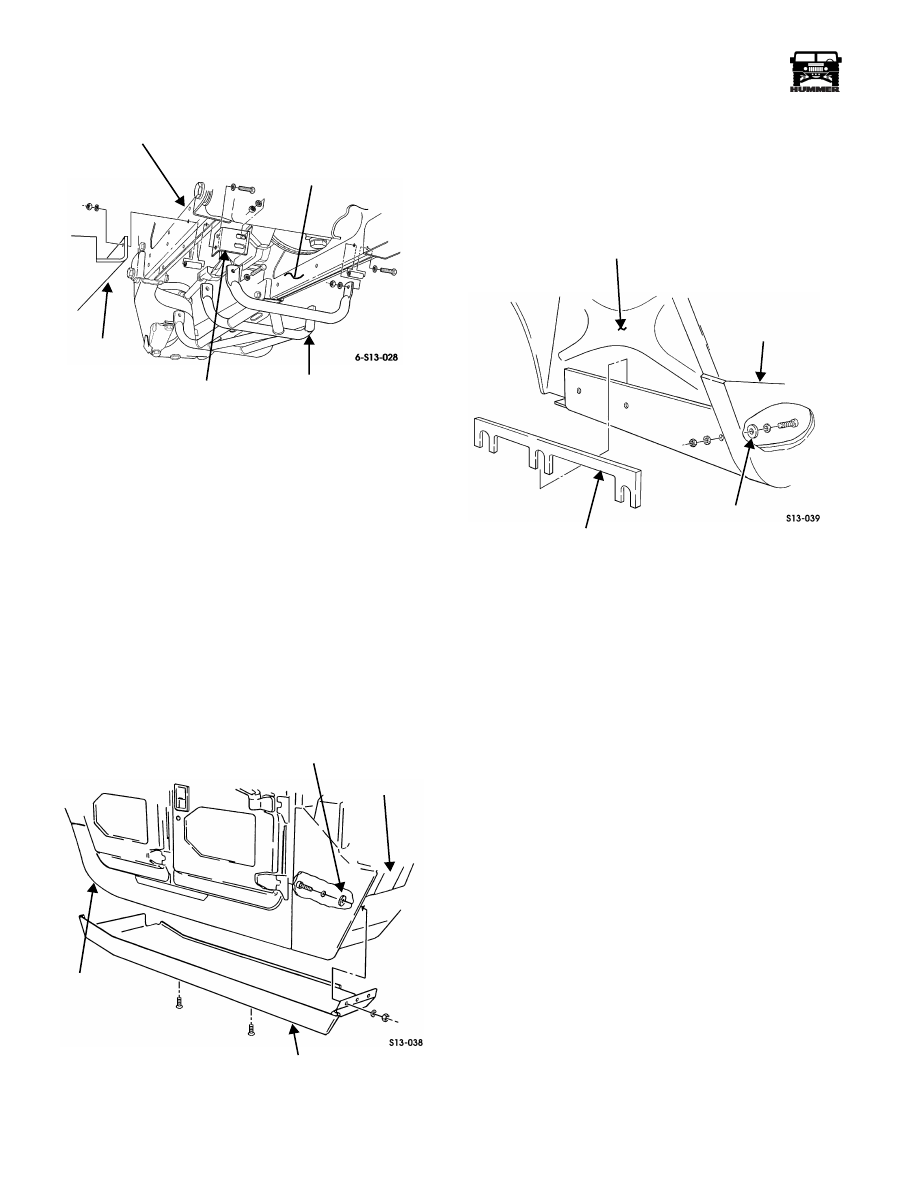
Figure 13-38: Transfer Case Shield
Rear Shield Replacement
Removal
1.
Remove three locknuts, washers, bolts, washers, and spac-
ers securing rear shield to rear-front crossmember. Discard
locknuts (Figure 13-39).
2.
Remove three locknuts, washers, bolts, washers, and
shield from mounting brackets. Discard locknuts.
3.
Remove six locknuts, washers, bolts, washers, spacers,
and three mounting brackets from rear-rear crossmember.
Discard locknuts.
Installation
1.
Install three mounting brackets on rear-rear crossmember
with six spacers, washers, bolts, washers, and locknuts.
Tighten locknuts to 24 lb-ft (33 N•m) (Figure 13-39).
2.
Position shield on mounting brackets and secure with
three washers, bolts, washers, and locknuts. Do not tighten
locknuts.
3.
Secure shield to rear-front crossmember with three
spacers, washers, bolts, washers, and locknuts. Tighten
bolts to 44 lb-ft (60 N•m).
4.
Tighten locknuts securing rear shield to mounting brackets
to 24 lb-ft (33 N•m)
FRONT
SHIELD
FRONT
CROSSMEMBER
INTERMEDIATE
SHIELD
TRANSFER CASE
SHIELD
CROSSMEMBER
13-18
Accessories
_____________________________________________________________
®
.
Figure 13-39: Rear Shield
ROCKER PANEL PROTECTION REPLACEMENT
Removal
NOTE: Removal of rocker panel protection is similar for both
sides. This procedure covers one side only.
1.
Remove outer kick panels (Section 10).
2.
Pull back carpet from front footwell and rear footwell
(4-door models only).
NOTE: Hex-head screws are secured in place with Loctite 242
and may require considerable effort to break loose.
3.
Remove nine hex-head screws securing rocker panel
protection to body. Support rocker panel protection with
floor jack (Figure 13-40).
Figure 13-40: Rocker Panel Protection
4.
Remove three nuts, washers, bolts, washers, and gaskets
securing rocker panel protection to front footwell. Discard
gaskets.
5.
Remove three nuts, washers, bolts, washers, and gaskets
securing spacer (if present) and rocker panel protection to
rear footwell (Figure 13-41).
Figure 13-41: Rear Footwell
CAUTION: Rocker panel protection is heavy. Remove with a
floor jack.
6.
Remove rocker panel protection from body.
7.
Inspect three retainer nuts on body. Discard if damaged.
Installation
CAUTION: Underbody skid panel is heavy. Raise into place
with a floor jack.
1.
Raise rocker panel protection to body.
2.
Secure rocker panel protection to rear footwell with three
gaskets, washers, bolts, washers, and nuts. Do not tighten
nuts (Figure 13-41).
3.
Secure rocker panel protection to front footwell with three
gaskets, washers, bolts, washers, and nuts. Do not tighten
nuts (Figure 13-40).
4.
Install spacer between rear footwell and rocker panel
protection if necessary. Tighten nuts at front and rear
footwells to 37 lb-ft (50 N•m) (Figures 13-40 and 13-41).
NOTE: Apply Loctite 242 to threads of hex-head screws.
5.
Remove floor jack and secure rocker panel protection to
body with nine hex-head screws. Tighten hex-head screws
to 37 lb-ft (50 N•m) (Figure 13-40).
6.
Push carpet back in place.
7.
Install outer kick panels (Section 10).
REAR-REAR
MOUNTING
REAR-FRONT
CROSSMEMBER
REAR SHIELD
CROSSMEMBER
BRACKET
AUXILIARY
FUEL TANK
SKID PLATE
FRONT
FOOTWELL
GASKET
BODY
ROCKER PANEL
PROTECTION
REAR FOOTWELL
GASKET
SPACER
ROCKER PANEL
PROTECTION

____________________________________________________________
Accessories 13-19
®
05745159
TRAILER TOWING
Figure 13-42: Trailer Wiring Connector and Dummy Plug Location
Trailer Jumper Harness
Hummer vehicles come from the factory equipped for easy in-
stallation of the trailer jumper harness. The trailer jumper har-
ness may be installed as part of the factory trailer towing
package or an add-on kit. Body wiring harnesses are designed
with a trailer wiring connector at the rear of the vehicle body
above the rear bumper (Figure 13-42). Rear bumpers are man-
ufactured with a cut-out for the trailer harness receptacle.
Installation
1.
Insert the trailer jumper harness through the rear bumper
cutout and bolt the receptacle in place (Figure 13-43).
2.
Remove the dummy plug and plug the trailer jumper
harness connector into the trailer wiring connector.
Trailer Brake Controller
Spare wires have been provided in the body harness and routed
from the instrument panel/fuse box area to the trailer connector
at the rear of the vehicle. Install the trailer brake controller us-
ing the manufacturer’s instructions.
The following information about the Hummer electrical system
is necessary for installation:
1.
Three shrink-wrapped wire leads can be found under the
instrument panel (Figure 13-44), they are:
a.
Yellow—power
b.
Red—stop light signal
c.
Dark blue—trailer brake
Figure 13-43: Trailer Jumper Harness Mounting
FRONT OF VEHICLE
TRAILER WIRING
REAR OF VEHICLE BODY
ABOVE REAR BUMPER
DUMMY PLUG
CONNECTOR
BODY WIRING HARNESS
TRAILER JUMPER HARNESS
RECEPTACLE
REAR BUMPER
TRAILER
WIRING
CONNECTOR
GASKET
13-20
Accessories
_____________________________________________________________
®
2.
The trailer brake circuit will not have power until a fuse
(of required amperage) is installed in fuse block position
7H—the far upper right hand corner of the fuse block.
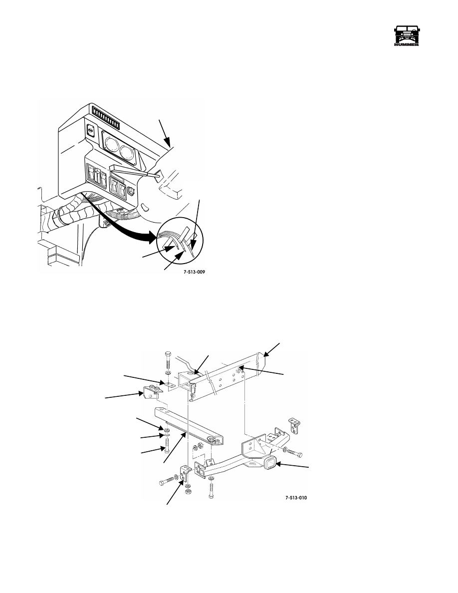
Figure 13-44: Trailer Brake Controller Wiring
TRAILER HITCH REPLACEMENT
Removal
1.
Remove locknuts, washers, receiver assembly mounting
blocks, bolts, and washers from body mount bracket
(Figure 13-45).
2.
Remove bolts, lockwashers, washers from lower brace
weld nuts. Remove brace from bumper and trailer hitch
mounting brackets.
3.
Remove bolts, washers, and trailer hitch from rear bumper
weld nuts.
Installation
1.
Position trailer hitch receiver on rear bumper and secure
with weld nuts, bolts and washers (Figure 13-45). Do not
tighten at this time.
2.
Secure trailer hitch to body mount bracket with locknuts,
washers, receiver assembly mounting blocks, bolts, and
washers.
3.
Install lower brace to bumper and trailer hitch mounting
bracket with bolts, lockwashers, washers and weld nuts.
4.
Tighten all locknuts to 90 lb-ft (122 N•m).
Figure 13-45: Trailer Hitch
STEERING COLUMN
DARK BLUE/
RED/STOP LIGHT
YELLOW/
TRAILER BRAKE
POWER
REAR BUMPER
TRAILER
HITCH
WELD NUT
RECEIVER
TRAILER HITCH
MOUNTING BRACKET
LOWER
BOLT
LOCKWASHER
WASHER
BRACE
RECEIVER ASSEMBLY
MOUNTING BLOCK
BODY
MOUNT
BRACKET
SIDE BRACKET
Нет комментариевНе стесняйтесь поделиться с нами вашим ценным мнением.
Текст