Hummer H1 (2002+). Manual — part 257
____________________________________________________________
Accessories 13-21
®
05745159
RUNNING BOARD REPLACEMENT
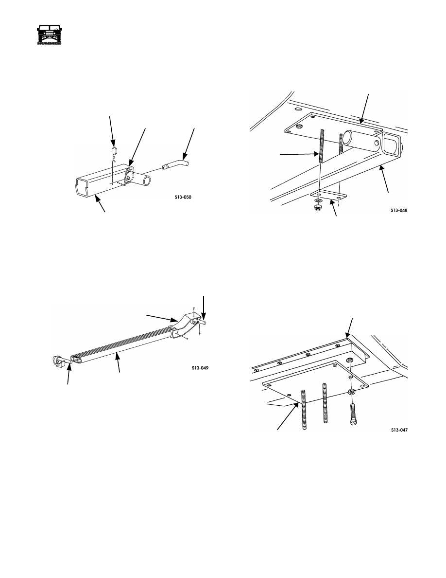
Removal
1.
Remove two clips and pins securing the right and left
curved tubes to the receiver (Figures 13-46 and 13-47).
Figure 13-46: Receiver
2.
Remove screw, nut, and screw securing the left end cap to
the left curved tube (Figure 13-47).
Figure 13-47: Left End Cap Secured
to Left Curved Tube
3.
Remove screw, nut, and screw securing the right end cap
to the right curved tube.
4.
Remove left curved tube from running board.
5.
Remove right curved tube from running board.
NOTE: If vehicle has rocker panel protection, remove the ex-
tra clamp plate used on the forward mounting area
between the mounting bracket and receiver.
6.
Remove four nuts, washers, and two clamp plates securing
two receivers to studs on mounting brackets
(Figure 13-48).
Figure 13-48: Receiver and Clamp Plate
NOTE: If vehicle does not have rocker panel protection, per-
form steps 7 and 8. If vehicle is equipped with rocker panel
protection, perform steps 9 and 10.
7.
Remove two bolts, lockwashers, and rear mounting
bracket from body (Figure 13-49).
Figure 13-49: Rear Mounting Bracket
CLIP
SPRING CLIP
PIN
RECEIVER
LEFT END CAP
LEFT CURVED
TUBE
RUNNING BOARD
ASSEMBLY
RIGHT CURVED
TUBE
REAR MOUNTING AREA SHOWN,
FRONT IS SIMILAR
MOUNTING BRACKET
STUD
RECEIVER
CLAMP
PLATE
RIGHT SIDE SHOWN,
LEFT SIDE OPPOSITE
BODY
MOUNTING
REAR
BRACKET
13-22
Accessories
_____________________________________________________________
®
8.
Remove four bolts, lockwashers, J-nuts, and front
mounting bracket from body (Figure 13-50).
Figure 13-50: Front Mounting Bracket and J-Nut
9.
Remove four bolts, lockwashers, and front mounting
bracket from rocker panel protection and body
(Figure 13-51).
Figure 13-51: Front Mounting Bracket
10. Remove two bolts, lockwashers, and rear mounting
bracket from rocker panel protection and body
(Figure 13-52).
Installation
NOTE: If vehicle does not have rocker panel protection, per-
form steps 1 and 2. If vehicle is equipped with rocker panel
protection, perform steps 3 and 4.
Figure 13-52: Rear Mounting Bracket
1.
Install front mounting bracket on body with four J-nuts,
lockwashers, and bolts. Tighten bolts to 29-31 lb-ft (39-42
N•m) (Figure 13-50).
2.
Install rear mounting bracket on body with two
lockwashers and bolts. Tighten bolts to 29-31 lb-ft (39-42
N•m) (Figure 13-49).
3.
Install front mounting bracket on rocker panel protection
and body with four lockwashers and bolts. Tighten bolts to
29-31 lb-ft (39-42 N•m) (Figure 13-51).
NOTE: If the vehicle does not have rocker panel protection,
an extra clamp plate must be used on the forward mounting
area between the mounting bracket and receiver.
4.
Install rear mounting bracket on rocker panel protection
and body with two lockwashers and bolts. Tighten bolts to
29-31 lb-ft (39-42 N•m) (Figure 13-52).
5.
Install receiver to studs on two mounting brackets with
two clamp plates, four washers, and nuts (Figure 13-48).
6.
Remove any extra mounting bracket stud lengths by
cutting the stud four thread lengths from the nut.
7.
Position right curved tube (with orange plastic bushing)
into running board. Ensure right curved tube points toward
the side of the running board with the “this side toward
frame” decal (Figure 13-47).
8.
Position left curved tube (with black plastic bushing) into
running board.
9.
Position right end cap on right curved tube with screw,
nut, and screw.
10. Position left end cap on the left curved tube with screw,
nut, and screw.
11. Position two spring clips on receiver. Ensure the spring
clips are positioned 180 degrees from each other
(Figure 13-46).
Secure the right and left curved tubes to the receiver with two
pins and clips.
LEFT SIDE SHOWN,
RIGHT SIDE OPPOSITE
MOUNTING
BRACKET
BODY
FRONT
FRONT OF
VEHICLE
MOUNTING
BODY
UNDERBODY
SKID PANEL
FRONT
BRACKET
FRONT OF
VEHICLE
MOUNTING BRACKET
CENTER HOLE

____________________________________________________________
Accessories 13-23
®
05745159
SIDE STEP BARS (TUBULAR)
Figure 13-53: Side Step Bar Installation
NOTE: This procedure covers the left side of the vehicle. The
procedure for the right side is the same.
Removal
1.
Remove the four bolts securing the tube brackets to the
support brackets (See Figure 13-53).
2.
Swing the step bar and angle bracket assembly down,
disengage the tube brackets from the support brackets and
remove the assembly.
3.
Remove four bolts securing the step bar to the tube bracket
and slide the step bar and end cap out of the tube bracket.
4.
Remove the rear seat (and subwoofer or jack bag if
equipped).
5.
Remove the rear lower trim panel behind the rear seat.
6.
Pull the rear floor mat up to expose the support bracket
mounting bolts in the rear wheel well area.
7.
Remove the two support bracket mounting nuts bolts and
washers in the rear wheel well.
8.
Remove the two bolts and washers going through the rear
support bracket into the rocker panel protection floor area
and remove the support bracket.
9.
Pull the front floor mat up to expose the support bracket
mounting bolts in the front wheel well area.
10. Remove the two support bracket mounting nuts bolts and
washers in the front wheel well.
11. Remove the two bolts and washers going through the front
support bracket into the rocker panel protection floor area
and remove the support bracket.
Installation
1.
Install the front and rear support brackets on the rocker panel
protection with bolts, washers and nuts (See Figure 13-53).
2.
Put the front and rear floor mats in position and install the
rear seat.
3.
Install the subwoofer or jack bag if equipped.
4.
Slide the tube brackets onto the bar in their respective
positions (angled bracket to the rear).
5.
Place the bar end caps on the ends of the bar and install the
bolts, washers and lockwashers through the tube brackets
into the bar. Do not tighten at this time.
6.
Hang the bar assembly on the tabs of the support brackets,
swing the bar up and secure the tube brackets to the
support brackets with bolts, washers, lockwashers and
nuts.
7.
Tighten the remaining hardware now.
9-S13-001
STEP
BAR
TUBE
BRACKET
SUPPORT
BRACKET

13-24
Accessories
_____________________________________________________________
®
ROOF RACK
Roof Rack Replacement
NOTE: The roof rack is available in three foot, six foot, and
nine foot lengths. The following procedure is for a six foot roof
rack installed on a station wagon. Three foot and nine foot pro-
cedures are similar.
Removal
WARNING: Roof rack is extremely heavy. Several peo-
ple may be required to remove and install rack safely.
Use care in determining ability to lift the rack. Failure
to do so may result in injury.
1.
Loosen eight support screws on clamps (Figure 13-54).
2.
Loosen eight locknuts securing clips to drip rails.
3.
Remove eight clips from under drip rails and remove rack
from vehicle.
Figure 13-54: Roof Rack Clamp
Installation
CAUTION: Clamps are made of aluminum. Overtightening
may cause the clamps to crack.
1.
Position roof rack on top of vehicle with rack ends toward
front and rear of vehicle (Figure 13-54).
2.
Position eight clips (on clamps) under drip rails and over
support screws. Tighten locknuts to 20-25 lb-in. (2-3
N•m).
3.
Tighten support screws on clamps.
Roof Rack Floor Piece Replacement
Removal
1.
Remove four end caps on floor piece.
2.
Remove four locknuts, washers, bolts, washers, and floor
piece from crossbars and rack ends (Figure 13-55).
Figure 13-55: Roof Rack Floor Piece
Installation
NOTE: Floor pieces should be positioned 5 inches (13 cm)
from the ends and 3 inches (8 cm) apart.
1.
Install floor piece on crossbars and rack ends with four
washers, bolts, washers, and locknuts. Tighten locknuts to
25 lb-ft (34 N•m) (Figure 13-55).
NOTE: Apply a small amount of adhesive to the inside periph-
ery of each end cap before installing it on the floor piece.
2.
Install four end caps on floor piece.
CLIP
CLAMP
DRIP RAIL
FRONT
OF
VEHICLE
END CAP
CROSSBAR
FLOOR PIECE
FRONT
OF
VEHICLE
Нет комментариевНе стесняйтесь поделиться с нами вашим ценным мнением.
Текст