Hummer H1 (2002+). Manual — part 198
______________________________________________________
Electrical System 12-19
®
05745159
BATTERY SPLASH SHIELD AND SEAL SERVICE
Splash Shield Removal
1.
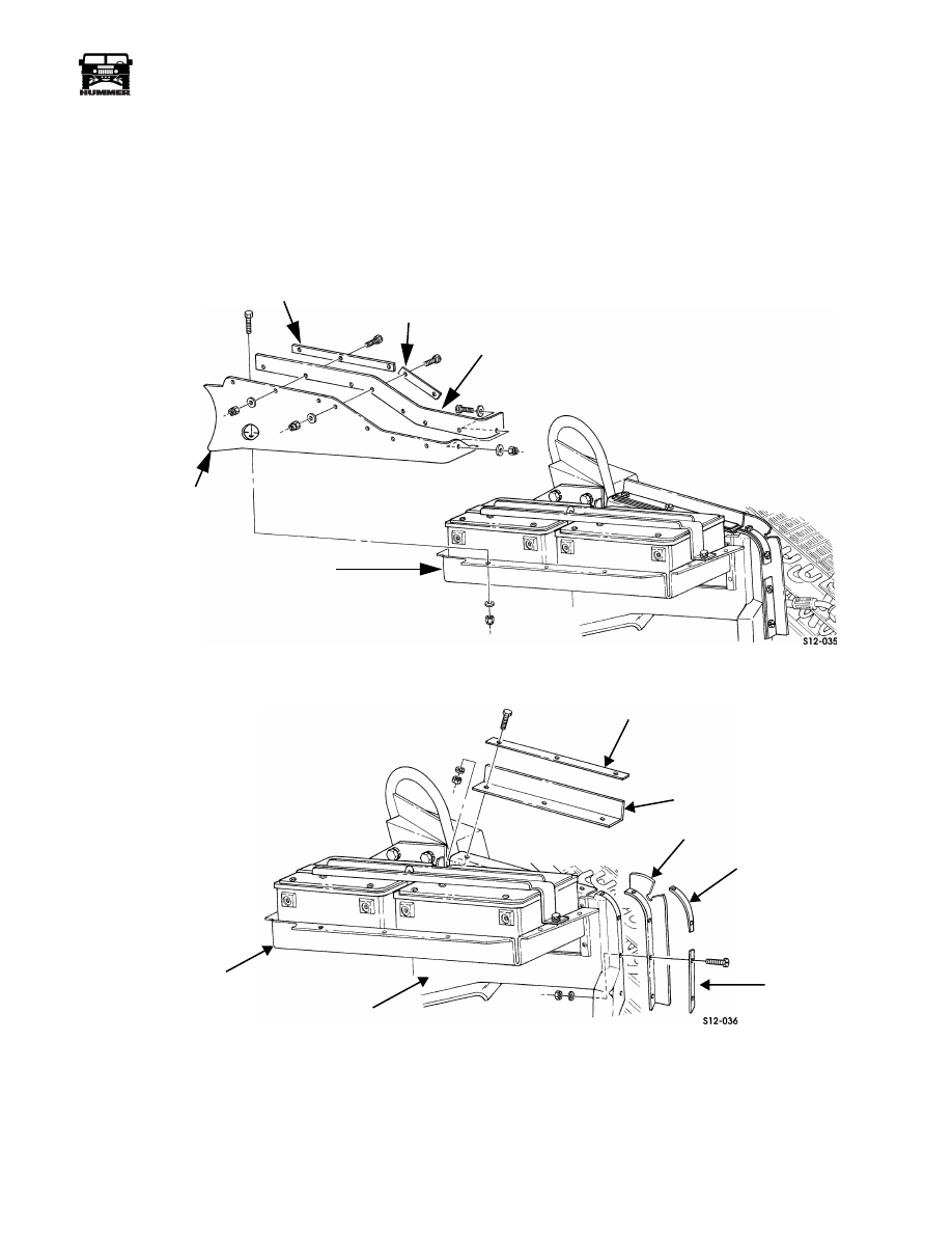
Remove upper splash shield and seal (Figure 12-32).
2.
Remove retainer bolts, and remove seal from battery tray
and lower shield (Figure 12-33).
3.
Remove lower splash shield bolts and remove lower
splash shield.
Figure 12-32: Upper Splash Shield Attachment
Figure 12-33: Seal and Retainer Attachment
UPPER
SPLASH SHIELD
RETAINER
RETAINER
SEAL
BATTERY TRAY
RETAINER
SEAL
BATTERY TRAY
LOWER
SPLASH SHIELD
SEAL
RETAINER
RETAINER
4-1-00
12-20
Electrical System
_______________________________________________________
®
Splash Shield Installation
1.
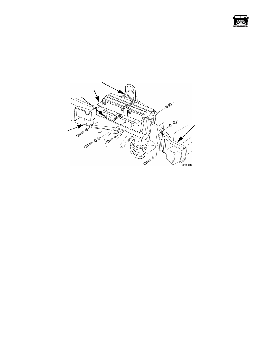
Position lower shield on bracket and install fasteners
(Figure 12-34).
2.
Install retainer on upper shield.
3.
Install upper shield on tray.
4.
Install seals and retainers (Figure 12-33).
Figure 12-34: Lower Splash Shield Removal/Installation
LOWER
SPLASH SHIELD
BRACKET
BATTERY TRAY
AIRLIFT BRACKET
FRAME
RAIL
4-1-00
______________________________________________________
Electrical System 12-21
®
05745159
MAJOR POWER DISTRIBUTION
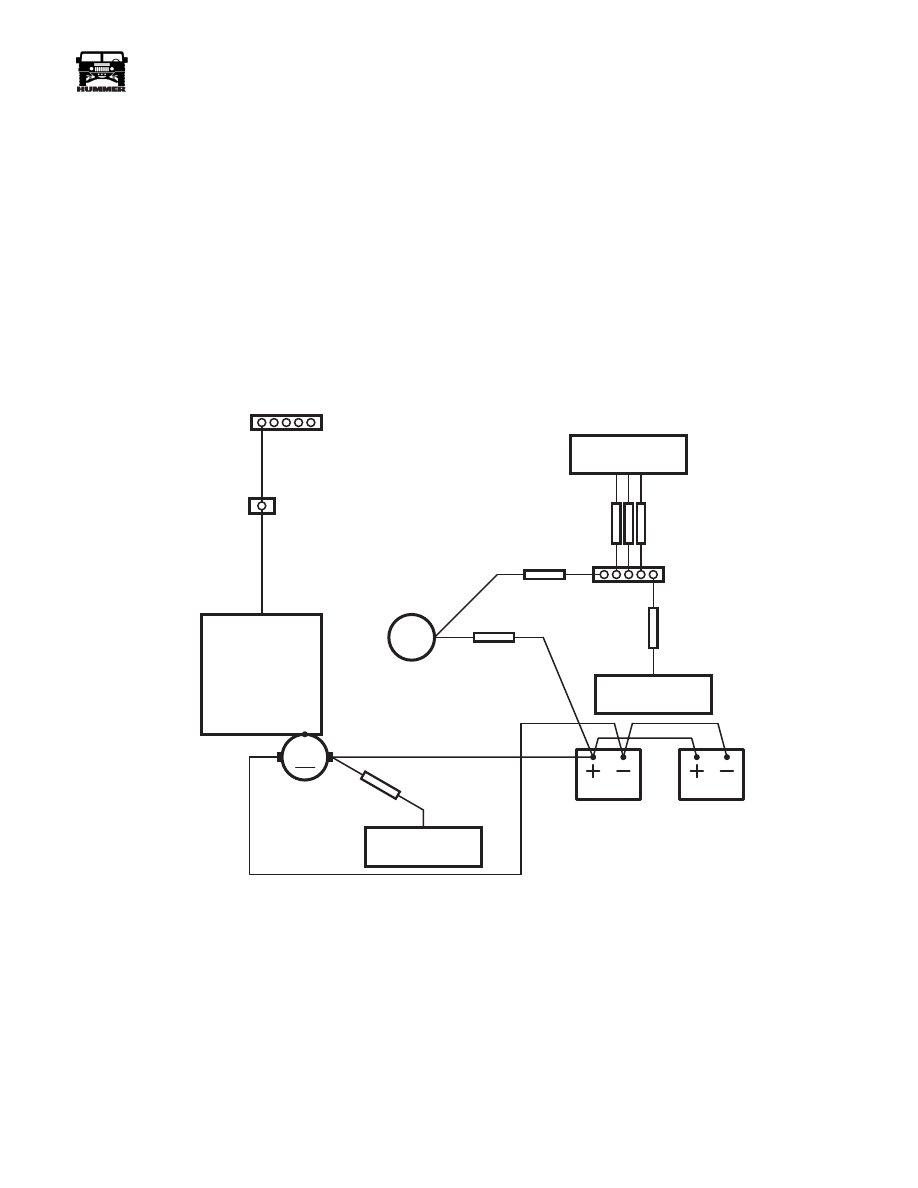
The following charts and illustrations convey how power is
distributed from the vehicle batteries to the fuse/relay centers.
Power is supplied to the fuse boxes from the batteries through
fusible links. Each fuse box has internal power busses that di-
rect the power to the fuses. The busses are indicated on the fuse
charts as follows: I = Ignition, B = Battery, A = Accessory, L
= Lamps.
The fuse charts contain a listing of the cavities in the fuse box,
the corresponding circuits, wire colors and gauges (ga.).
Power is supplied to an individual fuse by the buss indicated in
the left buss column. The circuit number (CKT No.) contains
two entries for a fuse: the power supply buss and the outgoing
circuit number. The numbers in the cavity column relate to
the cavities indicated on the fuse/relay cavity I.D. illustrations.
Using this information, you can determine which cavity of a
fuse is the power supply cavity and which other fuses are sup-
plied by the same buss.
Figure 12-35: Major Power And Ground Schematic
M
9-S12-088
FUSIBLE
LINK
GLOWPLUG
CONTROLLER
EXTERIOR
FUSE BOX
FUSIBLE
LINKS
FUSIBLE
LINK
FUSIBLE
LINK
INTERIOR
FUSE BOX
ENGINE
G4
G3
INTERIOR
GROUND BUSS
EXTERIOR FUSE BOX
GROUND BUSS
ALTERNATOR
BATTERY
BATTERY
STARTER
G1
FUSIBLE
LINK
EXTERIOR
POWER
BUSS
4-1-00

12-22
Electrical System
_______________________________________________________
®
ALTERNATOR
Removal
1.
Disconnect battery negative cable.
2.
Remove serpentine drivebelt from alternator pulley.
3.
Loosen pivot bolt and remove front and rear alternator
bolts (Figure 12-36).
4.
Pull alternator away from engine. Remove nut and
lockwasher and disconnect battery wires from battery
alternator terminal (Figure 12-37).
5.
Unlock and disconnect field wire (Figure 12-37).
6.
Remove pivot bolt and alternator from engine.
Installation
1.
Position alternator in bracket and install pivot bolt finger
tight.
2.
Connect battery wires to alternator. Secure with
lockwasher and nut. Tighten nut to 62-80 lb-in (7-9 N•m).
3.
Connect field wire to alternator.
4.
Move alternator into alignment with lower bracket and
install front and rear mounting bolts. Tighten bolts 18 lb-ft
(25 N•m).
5.
Tighten pivot bolt to 37 lb-ft. (50 N•m).
6.
Install serpentine drivebelt on pulley and adjust belt.
7.
Connect battery negative cable.
Figure 12-36: Alternator Mounting
Figure 12-37: Alternator Connections
ALTERNATOR
PIVOT
BOLT
ENGINE
BATTERY
TERMINAL
FIELD WIRES
BATTERY
WIRES
4-1-00
Нет комментариевНе стесняйтесь поделиться с нами вашим ценным мнением.
Текст