Hummer H1 (2002+). Manual — part 225

_____________________________________________________
Electrical System 12-125
®
05745159
Figure 2-121: Power Windows and Door Locks Door Harness
POWER DOOR LOCKS
POWER WINDOW
WINDOW BRACKET
DOOR ASSEMBLY
RETAINER
FRONT
DOOR
MOUNTING
DOOR
MOUNTING
BRACKET
BUSHING
BRACKET
REINFORCEMENT
DOOR
HARNESS
ACTUATOR
REGULATOR
BUSHING
4-1-00
12-126
Electrical System
______________________________________________________
®
POWER WINDOWS AND DOOR LOCKS REAR
DOOR HARNESS REPLACEMENT
Removal
1.
Remove center outer kick panel and lower B-pillar trim
(Section 10).
2.
Remove power windows switch from door.
3.
Remove rear door trim, vapor barrier, and moisture barrier
flap from door (Section 10).
NOTE:
Tag leads for installation.
4.
Disconnect 6-way harness connector from power windows
and door locks rear door jumper harness connector
(Figure 2-122).
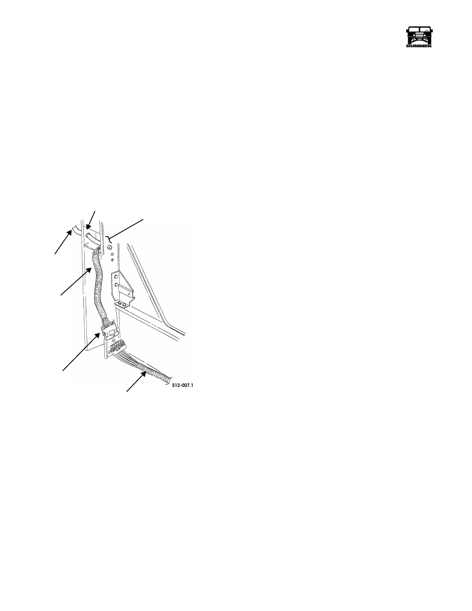
Figure 2-122: Rear Door Harness and
Rear Door Jumper Harness
5.
Remove harness wires from 6-way connector.
6.
Remove screw, nut and lockwasher assembly, and clamp
securing harness to B-pillar. Discard nut and lockwasher
assembly.
NOTE:
Lubricate bushings, grommet, and harness teflon
cover with silicone spray.
7.
Pull harness through B-pillar rubber grommet.
8.
Remove and inspect B-pillar rubber grommet. Replace if
damaged.
9.
Remove two self-tapping screws and harness mounting
bracket from door assembly (Figure 2-123).
10. Pull harness through door bushing.
11. Inspect door bushing and replace if damaged.
12. Remove harness mounting bracket and mounting bracket
bushing from harness. Inspect bushing and replace if
damaged.
13. Remove self-tapping screw and clamp securing harness to
door reinforcement.
14. Disconnect harness connector from power window
regulator (push locking tab up on bottom of connector).
15. Disconnect harness connector from power door lock
actuator.
16. Remove retainer securing harness to door assembly.
17. Remove tie strap and harness from door assembly. Discard
tie strap.
TEFLON TUBE
GROMMET
REAR DOOR
6-WAY CONNECTOR
REAR DOOR
B-PILLAR
HARNESS
JUMPER HARNESS
4-1-00
_____________________________________________________
Electrical System 12-127
®
05745159
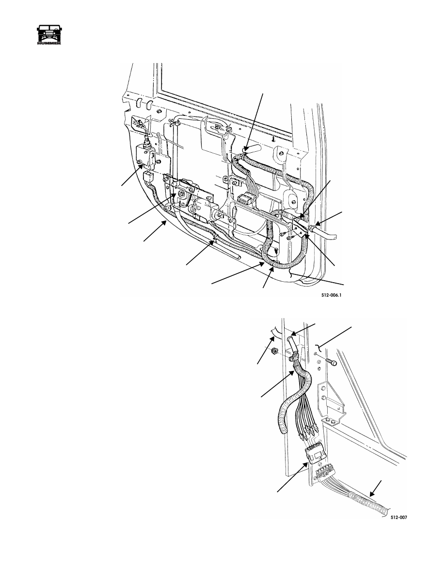
Figure 2-123: Rear Door Harness
Installation
NOTE:
Lubricate bushings, grommet, and harness teflon
cover with silicone spray.
1.
Route harness through harness mounting bracket, mount-
ing bracket bushing, and door bushing (Figure 2-123).
2.
Install harness mounting bracket on door assembly with
two self-tapping screws
3.
Route harness through B-pillar rubber grommet
(Figure 2-124).
NOTE:
When connecting harness wires to 6-way connector,
ensure wire colors align with mating connector wires.
4.
Connect harness wires to 6-way connector.
5.
Connect 6-way harness connector to power windows and
door locks rear door jumper harness connector.
6.
Secure harness to B-pillar with clamp, screw, and nut and
lockwasher assembly.
Figure 2-124: Rear Door Harness and Rear Door
Jumper Harness
TIE STRAP
MOUNTING
DOOR BUSHING
MOUNTING BRACKET
DOOR
CLAMP
DOOR HARNESS
RETAINER
DOOR ASSEMBLY
POWER
POWER DOOR
ACTUATOR
BRACKET
BUSHING
REINFORCEMENT
LOCK
WINDOW
REGULATOR
TEFLON TUBE
GROMMET
REAR DOOR
6-WAY CONNECTOR
REAR DOOR
“B” PILLAR
HARNESS
JUMPER HARNESS
4-1-00

12-128
Electrical System
______________________________________________________
®
7.
Connect harness connector to power window regulator
(Figure 2-123).
8.
Connect harness connector to power door lock actuator.
9.
Secure harness to door reinforcement with clamp and self-
tapping screw.
10. Secure harness to door assembly with retainer.
11. Secure harness to door assembly with tie strap.
12. Install moisture barrier flap, vapor barrier, and door trim
panel on door (Section 10).
13. Install power windows switch on door.
14. Install lower B-pillar trim and center kick panel (Section
10).
15. Connect battery ground cable (Section 12).
16. Check power windows and door locks for proper
operation.
17. Remove nut and ground lead from ground stud.
18. Disconnect two window and lock harness connectors from
door harness connectors (Figure 2-125).
19. Repeat step 10 for opposite side.
20. Remove B-pillar lower trim from both sides of the vehicle.
21. Disconnect lock and window harness connector from rear
door harness connector (HMCS, HMC4, HMCO)
22. Repeat step 12 for opposite side (HMCS, HMC4, HMCO).
23. Disconnect vertical door lock jumper from window and
door lock harness on the passenger side.(HMCS)
24. Remove tie straps securing harness to vehicle body
harness and remove harness. Discard tie straps.
Installation
1.
Route harness through instrument panel and along A- pil-
lar to both sides of vehicle.
2.
Connect harness connector to rear door harness connectors
on both sides of vehicle (HMCS, HMC4, HMCO).
3.
Connect vertical door lock jumper to window and door
lock harness on the passenger side.(HMCS)
4.
Connect two front lock and window harness connectors to
door harness connectors on both sides of vehicle.
5.
Install ground lead on ground stud with nut.
6.
Connect two lock and window harness leads to vehicle
body harness power leads.
7.
Connect two power windows and door locks harness
connectors to receiver harness connectors.
8.
Secure harness to vehicle body harness with tie straps.
9.
Install CTIS gauge panel
10. Install tachometer and clock harness into instrument panel
11. Install two gauge panels on instrument panel with eight
screws (Section 12).
12. Install console cover (Section 10).
13. Install front outer kick panels (Section 10).
14. Install crash pad (Section 10).
15. Check power windows and door lock for proper operation
Figure 2-125: Door Harness Connectors
A-PILLAR
DOOR HARNESS
CONNECTORS
WINDOW AND
LOCK HARNESS
CONNECTORS
4-1-00
Нет комментариевНе стесняйтесь поделиться с нами вашим ценным мнением.
Текст