Hummer H1 (2002+). Manual — part 142
________________________________________
Axles, Suspension, and Frame 9-29
®
05745159
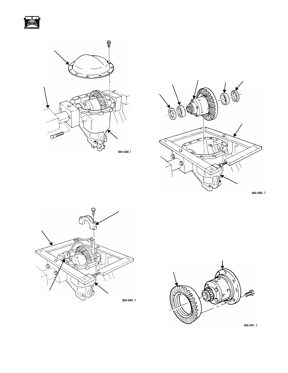
Figure 9-62: Axle Mounted In Holding Fixture
7.
Position housing so cover faces up. Remove twelve bolts
and cover from housing (Figure 9-62).
8.
Mark bearing caps and housing for assembly and remove
bearing caps (Figure 9-63).
Figure 9-63: Housing Spreader Mounting
9.
Install axle housing spreader J–3409-01 into holes in axle
holding fixture adapters and install dial indicator J–8001
to read from each end of housing as shown. Then set dial
indicator at 0.020 in. (0.5 mm).
CAUTION: Over-tightening of axle housing spreader will
damage axle housing.
10. Spread housing 0.010 in. (0.25 mm) and remove dial
indicator.
11. Remove differential assembly, two bearing cups, and
shims from housing (Figure 9-64). Tag bearing shims and
bearing cups for assembly.
Figure 9-64: Differential Assembly
12. Relieve pressure on axle housing spreader and remove
from housing.
CAUTION: To avoid damage, do not chisel or wedge ring
gear from axle assembly.
13. Remove eight bolts and ring gear from differential
assembly (Figure 9-65).
Figure 9-65: Ring Gear Removal
14. Rotate housing 90 degrees. Secure cover to housing with
two bolts (Figure 9-66).
DIFFERENTIAL
AXLE
AXLE HOLDING
FIXTURE J–3409-01
COVER
HOUSING
BEARING CAP
AXLE
HOUSING
SPREADER
HOUSING
DIAL INDICATOR
J–24385-01
J–8001
SHIM
BEARING CUP
DIFFERENTIAL
BEARING
SHIM
AXLE HOUSING
HOUSING
ASSEMBLY
CUP
SPREADER J–3409-01
DIFFERENTIAL ASSEMBLY
RING GEAR
9-30
Axles, Suspension, and Frame
_________________________________________
®
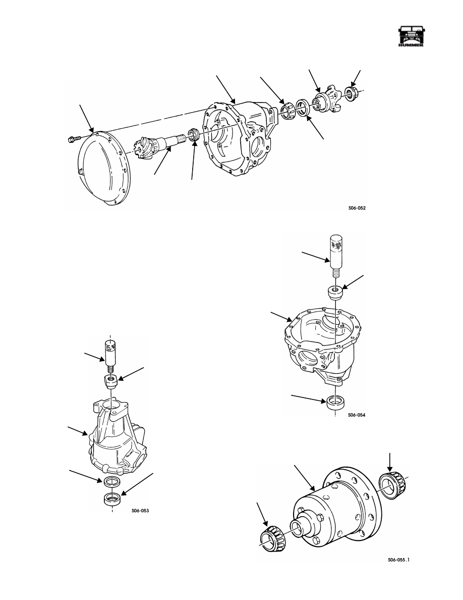
Figure 9-66: Axle Housing
15. Remove pinion nut and pinion yoke from pinion gear.
16. Drive pinion gear out of front pinion bearing.
17. Remove cover, pinion gear, and collapsible spacer from
housing. Discard collapsible spacer.
18. Remove pinion seal and front pinion bearing from
housing. Discard pinion seal.
19. Rotate front of housing upward 90 degrees. Using driver
handle J–8092 and bearing cup remover J–21786, remove
pinion rear bearing cup and pinion depth shim from
housing (Figure 9-67).
Figure 9-67: Pinion Rear Bearing Cup Removal
20. Rotate housing 180 degrees. Using driver handle J–8092
and pinion front bearing cup remover J–21787, remove
front pinion bearing cup from housing (Figure 9-68).
Figure 9-68: Pinion Front Bearing Cup Removal
Figure 9-69: Differential Side Bearing Removal
COVER
PINION
COLLAPSIBLE
HOUSING
FRONT
PINION SEAL
PINION YOKE
PINION NUT
SPACER
GEAR
PINION
BEARING
DRIVER
BEARING CUP
REMOVER
PINION
PINION REAR
BEARING CUP
HOUSING
DEPTH
SHIM
HANDLE
J–8092
J–21786
DRIVER
HANDLE
BEARING CUP
REMOVER
HOUSING
PINION FRONT
BEARING CUP
J–21787
J–8092
DIFFERENTIAL
SIDE BEARING
DIFFERENTIAL
ASSEMBLY
DIFFERENTIAL
SIDE BEARING
________________________________________
Axles, Suspension, and Frame 9-31
®
05745159
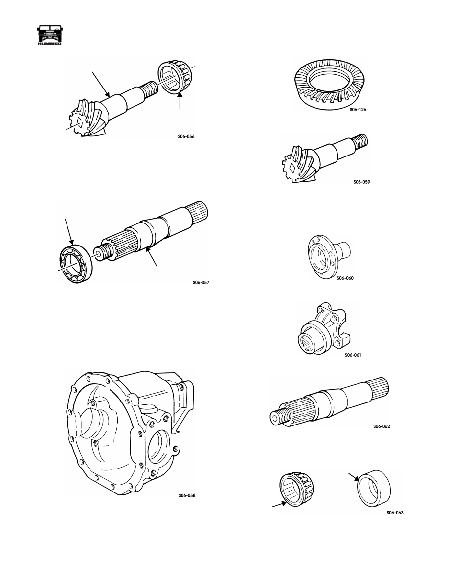
Figure 9-70: Pinion Bearing Removal
21. Remove two differential side bearings from differential
assembly (Figure 9-69).
22. Remove rear pinion bearing from pinion gear (Figure 9-70).
23. Remove bearing from output shaft (Figure 9-71).
Figure 9-71: Output Shaft Bearing Removal
Cleaning and Inspection
NOTE:
Clean all components. Examine for wear or damage
and replace if necessary.
1.
Inspect housing and all threaded holes for damage. Repair
any damaged threads with thread repair inserts. Replace
axle assembly if housing is damaged (Figure 9-72).
Figure 9-72: Housing
NOTE:
Ring and pinion gears must be replaced as matched set.
2.
Inspect splines and gear teeth on pinion gear and ring gear
for damage. Replace both pinion gear and ring gear if either
is damaged (Figure 9-73: and Figure 9-74:).
Figure 9-73: Ring Gear
Figure 9-74: Pinion Gear
3.
Inspect splines and sealing surfaces on output flanges,
pinion yoke, and output shaft for damage (Figure 9-75)
through (Figure 9-77).
Figure 9-75: Output Flange
Figure 9-76: Pinion Yoke
Figure 9-77: Output Shaft
4.
Inspect all bearings and bearing cups for damage
(Figure 9-78).
Figure 9-78: Bearing and Bearing Cup
5.
Inspect differential assembly case for damage
(Figure 9-79).
PINION GEAR
REAR PINION BEARING
BEARING
OUTPUT SHAFT
BEARING
BEARING
CUP
9-32
Axles, Suspension, and Frame
_________________________________________
®
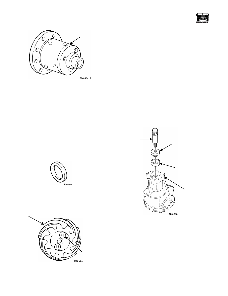
Figure 9-79: Differential Assembly
Axle Assembly
NOTE: PINION DEPTH SETTING
: Pinion gear depth is the
distance from the end face of the pinion to the center line of the
output shafts. The dimension is controlled by shims between
pinion gear rear bearing cup and differential housing. The pin-
ion gear is etched with two identifying numbers. The first num-
ber identifies ring gear and pinion gear as a matched set, and
the second number represents pinion depth variance. The sec-
ond number is preceded by a plus (+) or minus (-) which repre-
sents the amount the gear set varies from the standard setting of
2.547 in. (6.46 cm). If using original gear set, use original pin-
ion depth shim as a starter shim and proceed to step 4.
1.
Measure thickness of original pinion depth shim and
record for reference (Figure 9-80).
Figure 9-80: Pinion Depth Shim
2.
Check pinion depth variance number marked on old and
new pinion gears and record (Figure 9-81). Refer to
Table 4.
Figure 9-81: Pinion Depth Variance Number
Location
NOTE:
If the old pinion is marked -3 and the new pinion is
marked +2, the procedure would be as follows: Refer to Old
Pinion Marking column at left side of table and locate -3 in this
column. Then read to right, across table, until under +2 in New
Pinion Marking column. The box where two columns intersect
is amount of shim thickness change required. In this case, the
number in the intersecting box is -0.005 in. (0.13 mm) which
represents the amount to be subtracted from the old shim thick-
ness. If the box number had been a (+) figure, this amount
would be added to the old shim thickness. The actual pinion
depth measurement must be performed and final shim thick-
ness adjusted as necessary. Pinion shims are available from
0.084-0.111 in. (2.13-2.82 mm) in increments of 0.0005 in.
(0.0127 mm).
3.
Refer to Old and New Pinion Marking columns on pinion
variance table. Note on table where old and new pinion
depth variances intersect. This will determine amount to
be added or subtracted from original pinion depth shim for
desired pinion depth starter shim.
4.
Rotate housing so front pinion bearing cup bore faces up
(Figure 9-82).
Figure 9-82: Pinion Front Bearing Cup
Installation
DIFFERENTIAL
ASSEMBLY
PINION GEAR
PINION DEPTH
VARIANCE
NUMBER
DRIVER
HANDLE
BEARING CUP
INSTALLER
PINION FRONT
BEARING CUP
HOUSING
J–8092
J–8611-01
Нет комментариевНе стесняйтесь поделиться с нами вашим ценным мнением.
Текст