Hummer H1 (2002+). Manual — part 141
________________________________________
Axles, Suspension, and Frame 9-25
®
05745159
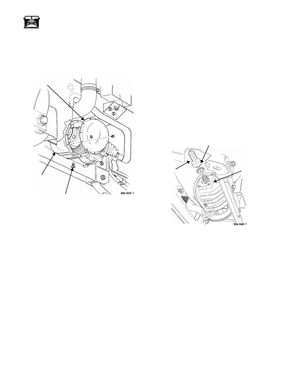
AXLE ASSEMBLY COVER SERVICE
Removal
1.
Remove drainplug from axle assembly and drain axle
assembly (Figure 9-53).
2.
Remove twelve bolts and cover from axle assembly.
Figure 9-53: Axle Assembly Cover Service
Cleaning and Inspection
NOTE:
Clean all components, examine for wear or damage,
and replace if necessary.
1.
Clean axle assembly cover, bolts, and axle assembly with
solvent (Figure 9-53).
2.
Inspect axle assembly cover for cracks, wear, or breaks.
Installation
1.
Apply RTV sealant to cover sealing surface and secure
cover to axle assembly with twelve bolts. Tighten bolts to
16 lb-ft (22 N•m).
2.
Thread drainplug into axle assembly and tighten to 13-18
lb-ft (18-25 N•m) (Figure 9-53).
3.
Fill axle assembly to proper oil level (Section 1).
AXLE OUTPUT SHAFT SEAL REPLACEMENT
Removal
1.
Remove brake caliper and yoke from caliper adapter (dis-
connect park brake cable from rear calipers) and support
caliper to the side being careful not to kink brake line.
2.
Disconnect halfshaft at the axle flange and swing off to
the side.
3.
Remove the brake rotor.
4.
Remove the axle output flange retaining nut and the
flange.
5.
Support the axle assembly, disconnect and move the axle
assembly support bracket over to gain access to the output
seal.
6.
Remove output shaft seal from axle (Figure 9-54).
Figure 9-54: Axle Output Shaft Seal Replacement
Installation
1.
Using seal installer J–38869, install output shaft seal in
axle assembly (Figure 9-54).
2.
Install axle assembly support bracket.
3.
Install axle output shaft flange and nut using Loctite 242
(or equivalent) and torque to 166-196 lb ft (224-265 N.m).
4.
Install brake rotor and halfshaft. Use bolts with preapplied
Loctite or original bolts with Loctite 272 (or equivalent),
cam-lock washers and torque 57 lb ft (77 N.m).
5.
Install brake caliper and yoke using Loctite 272 (or
equivalent) (connect park brake cable on rear calipers) and
torque to 40 lb ft (54 N.m).
AXLE COVER
AXLE ASSEMBLY
DRAINPLUG
AXLE SHAFT
OUTPUT
SHAFT
SEAL
AXLE
AND SEAL
INSTALLER
ASSEMBLY
J–38869
9-26
Axles, Suspension, and Frame
_________________________________________
®
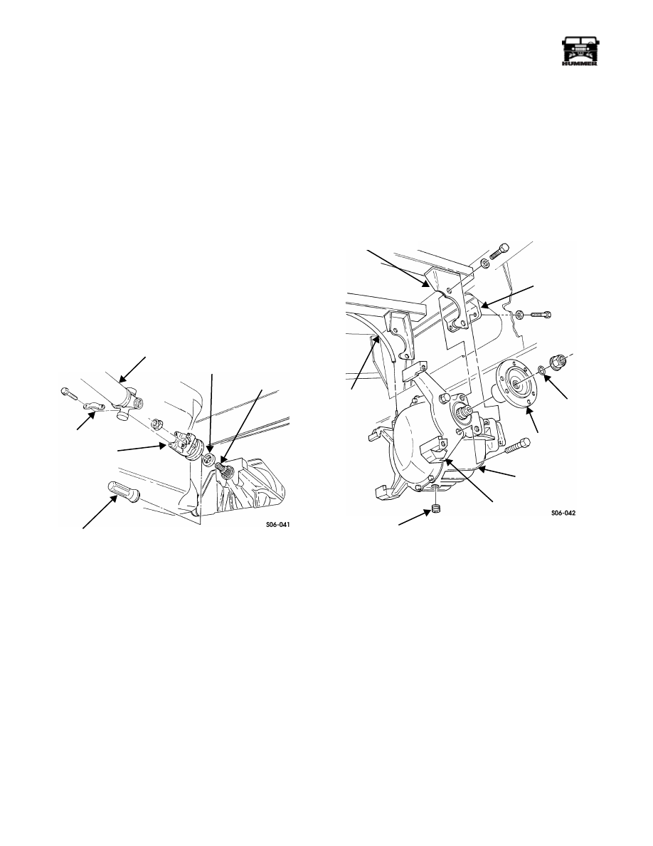
PINION SEAL REPLACEMENT
NOTE:
Removal and installation procedures for pinion seals
are basically the same for front and rear axle assemblies. This
procedure covers the rear axle assembly pinion seal.
Removal
1.
Remove six bolts, cam-lock washers, and halfshaft from
each output flange rotor.
2.
Remove four bolts, two straps, and rear propeller shaft
from pinion yoke (Figure 9-55).
3.
Using a lb-in torque wrench, measure torque required to
rotate pinion and record measurement.
4.
Count and record number of exposed threads on end of
pinion and mark locknut and pinion for assembly.
5.
Remove locknut and pinion yoke from pinion.
6.
Remove pinion seal from pinion.
Figure 9-55: Pinion Seal Replacement
Installation
1.
Using yoke seal installer J–29162, install pinion seal on
pinion (Figure 9-55).
2.
Secure pinion yoke to pinion with locknut.
3.
Tighten locknut to original position.
4.
Tighten locknut in small increments, until torque required
to rotate pinion exceeds original measurement by 2 lb-in
(0.2 N•m).
5.
Secure rear propeller shaft to pinion yoke with four bolts
and two straps. Tighten bolts to 27 lb-ft (37 N•m).
6.
Apply Loctite 272 to halfshaft mounting bolts.
7.
Secure halfshaft to each output flange and rotor with
twelve cam-lock washers and six bolts. Tighten to 57 lb-ft
(77 N•m).
AXLE ASSEMBLY REPLACEMENT
Removal
NOTE:
Removal and installation procedures are basically the
same for front and rear axle assemblies. This procedure covers
both front and rear axle assemblies except where noted.
1.
Remove service brake rotors (Section 7).
2.
Remove drainplug from axle assembly. Allow oil to drain
and install drainplug (Figure 9-56).
Figure 9-56: Rear Axle Assembly Mounting
3.
Remove four bolts, two straps, and rear propeller shaft
from pinion yoke (Figure 9-57).
4.
Remove rear propeller shaft from transfer case.
NOTE:
No washers are required when securing front axle as-
sembly to mounting bracket.
5.
Remove two bolts and washers securing axle assembly to
mounting bracket (Figure 9-56).
6.
Remove two locknuts, four O-ring seals and two output
flanges from axle assembly. Discard locknuts and O-ring
seals.
REAR
STRAP
PINION YOKE
YOKE SEAL
PINION SEAL
PINION
INSTALLER
PROPELLER
SHAFT
J–29162
VENT LINE
MOUNTING
RUBBER
OUTPUT
AXLE ASSEMBLY
BRAKE
DRAINPLUG
CALIPER
ADAPTER
FLANGE
WASHER
BRACKET
AXLE ASSEMBLY
SUPPORT BRACKET

________________________________________
Axles, Suspension, and Frame 9-27
®
05745159
WARNING: Axle assembly must be supported during
removal and installation. Failure to do this may cause
personal injury or damage to equipment.
7.
Support axle assembly.
8.
Remove four bolts and washers securing axle assembly to
side mounting brackets.
9.
Lower axle assembly slightly and disconnect vent line
from axle assembly.
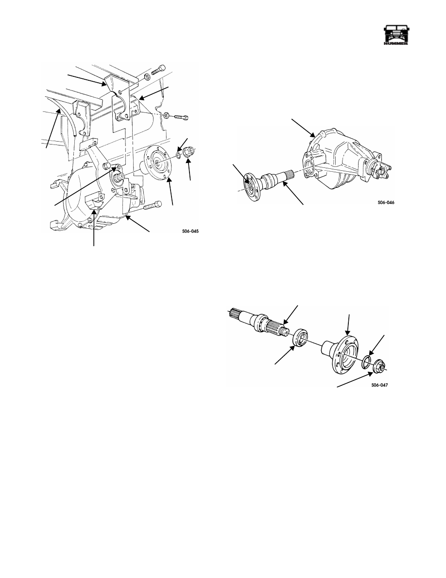
10. Remove axle assembly.
11. Remove four bolts and two brake caliper adapters from
axle assembly.
12. Using a lb-in torque wrench, measure torque required to
rotate pinion and record measurement.
13. Count and record number of exposed threads on end of
pinion and mark locknut and pinion for assembly.
14. Remove locknut and rear pinion yoke from axle assembly
(Figure 9-58).
Figure 9-57: Rear Propeller Shaft Removal
Figure 9-58: Pinion Yoke Removal
Installation
1.
Secure rear pinion yoke to axle assembly with locknut
(Figure 9-58).
2.
Tighten locknut in small increments, until torque required
to rotate pinion yoke exceeds original measurement by 2
lb-in (0.2 N•m).
3.
Apply thread-locking compound to axle assembly tapped
holes. Secure two brake caliper adapters to axle assembly
with four bolts. Tighten bolts to 110-140 lb-ft (149-190
N•m) (Figure 9-59).
TRANSFER CASE
PINION YOKE
STRAP
REAR
PROPELLER
SHAFT
AXLE ASSEMBLY
REAR PINION YOKE
LOCKNUT
9-28
Axles, Suspension, and Frame
_________________________________________
®
Figure 9-59: Rear Axle Assembly Installation
4.
Raise axle assembly into place and connect vent line.
5.
Apply thread-locking compound to axle assembly tapped
holes. Install axle assembly on side mounting brackets
with four washers and bolts.
6.
Secure two output flanges and two seals to axle assembly
with two locknuts. Tighten locknuts to 165-195 lb-ft (224-
264 N•m).
NOTE:
No washers required when securing front axle assem-
bly to mounting bracket.
7.
Apply thread-locking compound to bolts. Install two
washers, bolts, and axle assembly to mounting bracket.
8.
Tighten six bolts securing axle assembly to brackets to
110-139 lb-ft (149-188 N•m).
9.
Install rear propeller shaft in transfer case (Figure 9-57).
10. Secure rear propeller shaft to pinion yoke with four bolts
and two straps. Tighten bolts to 60 lb-ft (81 N•m)
(Figure 9-57).
11. Install service brake rotors (Section 7).
12. Fill axle assembly to proper oil level (Section 1).
13. Install vent line to axle assembly.
AXLE ASSEMBLY REPAIR
Disassembly
1.
Remove axle assembly.
2.
Loosen locknut on output shaft assembly (Figure 9-60).
Figure 9-60: Output Shaft Assembly Removal
3.
Using a slide hammer, remove output shaft assembly from
axle assembly.
4.
Remove locknut, seal washer, output flange and output
shaft seal from output shaft. Discard seal washer, output
shaft seal, and locknut (Figure 9-61).
Figure 9-61: Output Shaft Assembly Breakdown
5.
Repeat steps 2 through 4 for opposite side.
6.
Secure two axle holding fixture adapters to housing with
four bolts. Place housing in holding stand (Figure 9-62).
SIDE
VENT LINE
TAPPED
BRAKE
AXLE ASSEMBLY
OUTPUT
MOUNTING
MOUNTING
BRACKET
HOLES
BRACKET
FLANGE
CALIPER
ADAPTER
SEAL
LOCKNUT
WASHER
AXLE ASSEMBLY
OUTPUT SHAFT ASSEMBLY
LOCKNUT
OUTPUT SHAFT
OUTPUT SHAFT SEAL
OUTPUT
FLANGE
SEAL
LOCKNUT
WASHER
Нет комментариевНе стесняйтесь поделиться с нами вашим ценным мнением.
Текст