Hummer H1 (2002+). Manual — part 140
________________________________________
Axles, Suspension, and Frame 9-21
®
05745159
GEARED HUB SPINDLE STUD REPLACEMENT
WARNING: Always wear eye protection when replac-
ing spindle studs. Severe eye injury may result if metal
chips contact eyes.
Removal
1.
Remove wheel.
2.
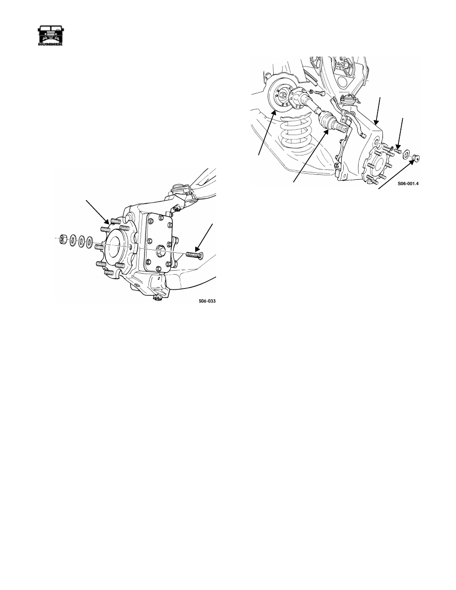
Rotate spindle to allow clearance for removal of stud from
spindle (Figure 9-44).
3.
Drive stud from spindle. Discard stud.
Figure 9-44: Geared Hub Spindle Stud Removal
Installation
1.
Install stud in spindle (Figure 9-44).
2.
Install three flat washers and hex nut on stud.
3.
Tighten hex nut until head on stud seats against spindle.
4.
Remove and discard hex nut and three flat washers.
HALFSHAFT BOOT REPLACEMENT
Removal
NOTE:
Inner and outer boots are replaced together. The inner
CV joint is disassembled to gain access to the halfshaft boots.
1.
Remove wheel.
2.
Remove access plug and washer from geared hub
(Figure 9-45).
3.
Remove six bolts, lockwashers, and halfshaft from rotor.
4.
Remove halfshaft retaining bolt, lockwasher, and halfshaft
from geared hub.
Figure 9-45: Halfshaft Retaining Bolt
5.
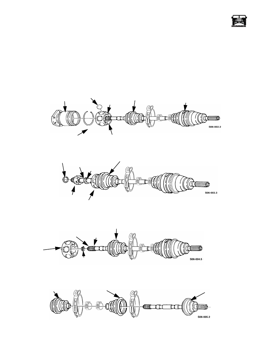
Loosen two clamps securing inner boot to inner joint
housing and shaft (Figure 9-46).
6.
Slide inner boot toward outer joint along shaft.
NOTE:
Remove excess grease from bearing assembly.
7.
Clamp shaft in soft-jawed vise.
8.
Remove retaining ring from inner joint housing by forcing
clip up chamfer on inside of housing.
9.
Remove housing and six ball bearings from bearing
assembly.
10. Move outer race up on shaft to allow for better access to
inner race (Figure 9-48).
11. Locate snap ring adjacent to inner race. Remove snap ring
from groove and slide up on shaft (Figure 9-48).
12. Tap inner race up on shaft to expose retaining clip.
13. Remove retaining clip and inner race from shaft.
14. Remove outer race, snap ring, and inner boot from shaft.
(Figure 9-48).
15. Remove two clamps and outer boot from shaft.
Cleaning and Inspection
NOTE:
Clean all components, examine for wear or damage,
and replace halfshaft if necessary.
1.
Clean all metallic parts with solvent.
2.
Inspect halfshaft assembly for damage or wear, and
replace if damaged or worn.
SPINDLE
STUD
ROTOR
HALFSHAFT
GEARED
HALFSHAFT
ACCESS
PLUG
HUB
RETAINING
BOLT
9-22
Axles, Suspension, and Frame
_________________________________________
®
Installation
1.
Position outer boot and two clamps on shaft near outer
joint.
2.
Apply packet of grease to outer joint.
3.
Position outer boot over outer joint housing and secure
clamp with boot banding tool J–22610.
4.
Secure smaller clamp on boot and shaft with tool J–22610.
5.
Clamp shaft in vise with protective jaws.
6.
Position two clamps on shaft (Figure 9-49).
7.
Install inner boot on shaft. Push boot past groove on shaft.
8.
Install the snap ring and retaining clip into grooves on
shaft (Figure 9-48).
9.
Align chamfer splines of inner bearing assembly with
spline of shaft. Use press or rawhide hammer to install
inner race until it snaps in place - flush against spacer ring.
10. Position six ball bearings into bearing assembly and retain
with a slight amount of grease (Figure 9-46).
Figure 9-46: Halfshaft Boot Replacement
Figure 9-47: Halfshaft Boot Replacement
Figure 9-48: Halfshaft Boot Replacement
Figure 9-49: Halfshaft Boot Replacement
INNER JOINT HOUSING
RETAINING RING
BEARING
INNER BOOT
OUTER
RACE
INNER RACE
OUTER JOINT
RETAINING CLIP
SHAFT
INNER BOOT
OUTER RACE
SNAPRING
INNER RACE
BEARING
SNAP RING
SNAP RING
INNER BOOT
GROOVE
ASSEMBLY
RETAINING
CLIP
GROOVE
INNER BOOT
OUTER BOOT
OUTER
CV JOINT
ASSEMBLY
________________________________________
Axles, Suspension, and Frame 9-23
®
05745159
11. Position joint inner housing over bearing assembly.
NOTE:
Ensure all ball bearings are in the tracks of the inner
joint.
12. Secure retainer ring in groove of inner joint housing.
13. Fill inner joint with grease from grease packet.
14. Move inner boot on shaft until boot seats in groove of
shaft and inner joint housing.
15. Secure inner boot on shaft and housing with clamps.
Tighten clamps with crimping tool J–22610.
16. Slide halfshaft splines into geared hub.
17. Apply thread-locking compound to halfshaft retaining bolt
and secure halfshaft to geared hub with lockwasher and
halfshaft retaining bolt. Tighten halfshaft retaining bolt to
37 lb-ft (50 N•m) (Figure 9-45).
18. Install washer and access plug into geared hub. Tighten
access plug to 8-13 lb-ft (11-18 N•m).
NOTE:
Ensure all six bolt holes in the rotor align with holes
in output flange. Make sure mounting holes and bolts are
cleared of old Loctite.
19. Apply Loctite 272 to six bolts. Secure halfshaft to rotor
with twelve lockwashers and bolts. Tighten bolts to 48 lb-
ft (65 N•m).
20. Install wheel.
AXLE VENT LINE REPLACEMENT
NOTE:
Axle vent line replacement procedures are basically
the same. This procedure covers the rear axle vent line.
Removal
1.
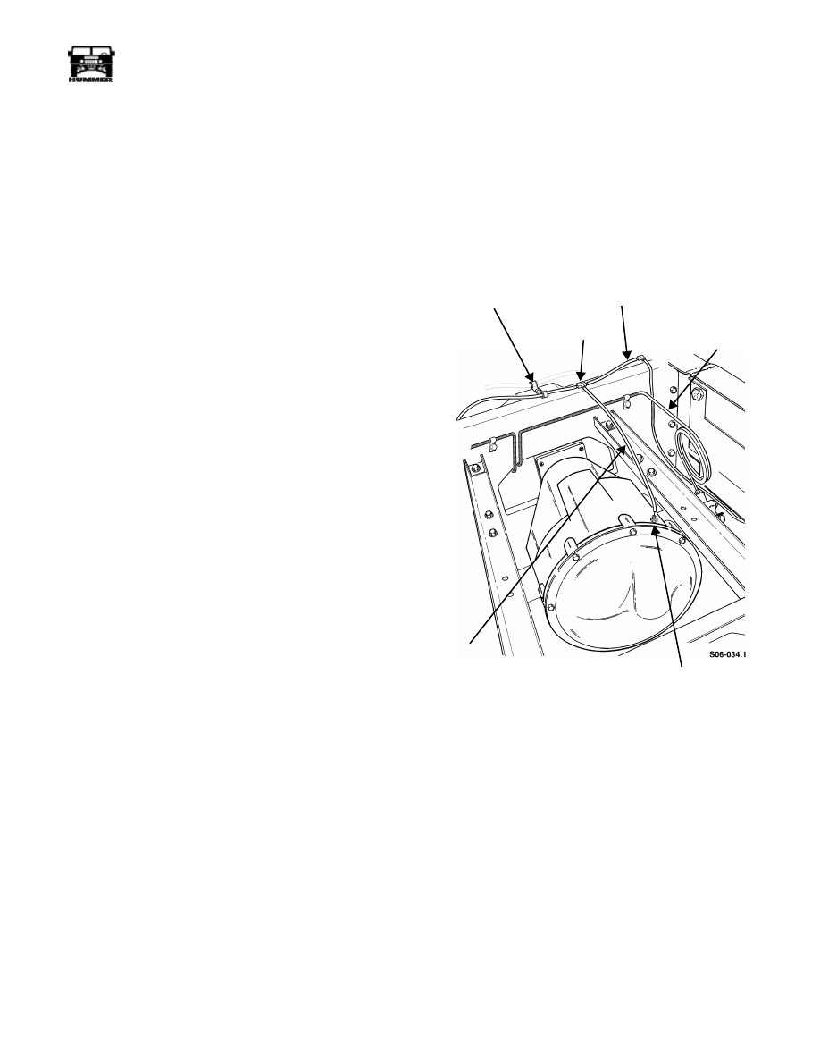
Disconnect vent line from axle fitting and tee fitting and
remove vent line (Figure 9-50).
2.
Remove two line clips and vent line from brake line.
3.
Disconnect vent line from two tee fittings and remove vent
line.
Figure 9-50: Axle Vent Line Location
Installation
1.
Install vent line and connect to two tee fittings
(Figure 9-50).
2.
Secure vent line to brake line with two line clips.
3.
Connect vent line to axle fitting and tee fitting.
LINE CLIPS
VENT LINE
TEE FITTING
BRAKE LINE
AXLE FITTING
VENT LINE
9-24
Axles, Suspension, and Frame
_________________________________________
®
GEARED HUB VENT LINE REPLACEMENT
NOTE:
All geared hub vent line replacement procedures are
basically the same. This procedure covers the right rear geared
hub vent line.
Removal
NOTE:
Speed sensor lead is retained by the vent line clamps
and should be removed and reinstalled with care when replac-
ing the vent line.
1.
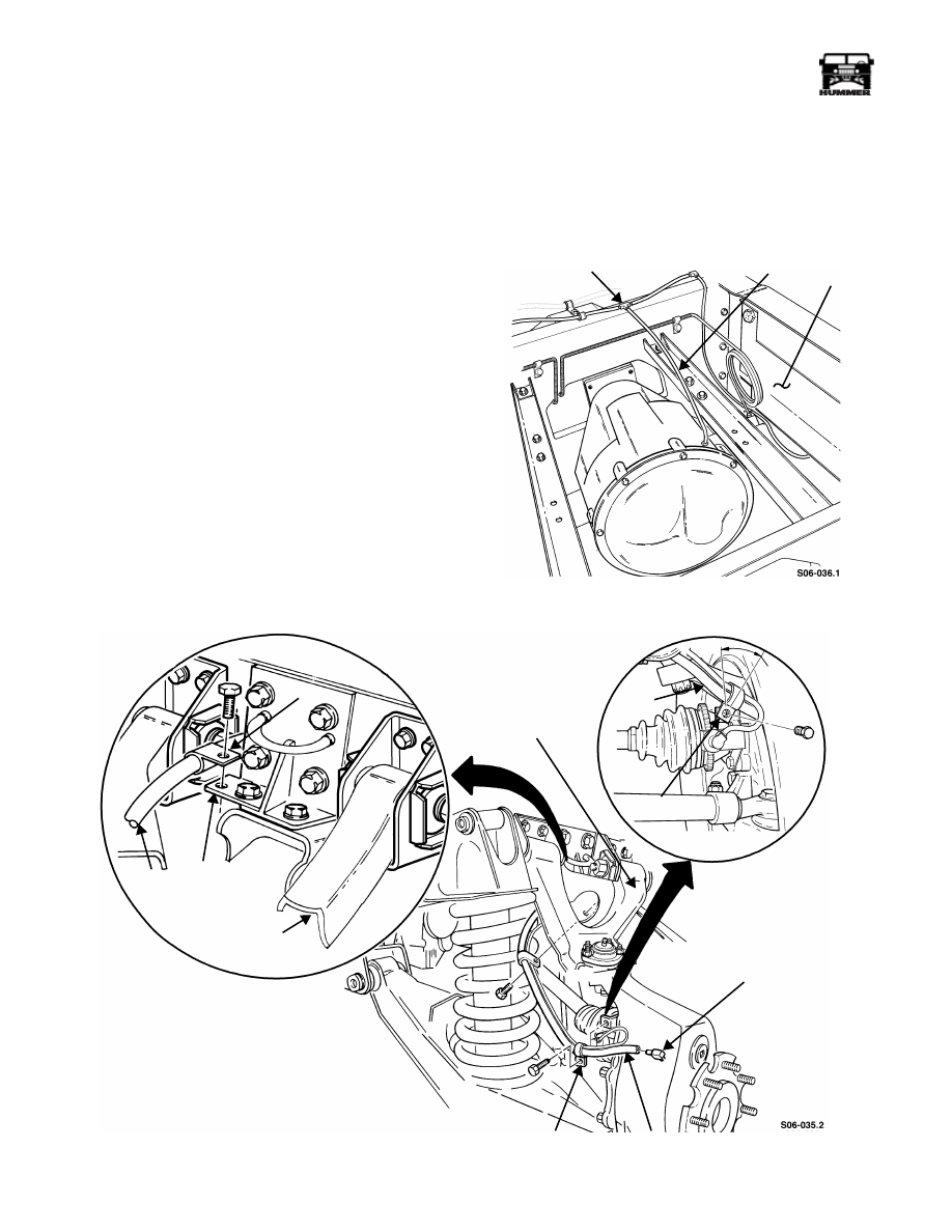
Disconnect vent line from geared hub fitting (Figure 9-52).
2.
Remove bolt, clamp, and vent line from bracket.
3.
Remove bolt, clamp, and vent line from control arm.
4.
Remove bolt, clamp, and vent line from bracket.
5.
Remove bolt, clamp, and vent line from frame
(Figure 9-51).
6.
Disconnect vent line from tee fitting.
Installation
1.
Secure vent line to frame with clamp and bolt
(Figure 9-51).
2.
Secure vent line to bracket with clamp and bolt
(Figure 9-52).
3.
Connect vent line to tee fitting and geared hub fitting.
4.
Secure vent line to control arm with clamp and bolt
(Figure 9-52).
NOTE:
Position clamp at a 45 degree angle toward the wheel
before securing with bolt.
5.
Secure vent line to bracket with clamp and bolt.
Figure 9-51: Vent Line
Figure 9-52: Geared Hub Vent Line Positioning
TEE FITTING
VENT LINE
FRAME
CLAMP
BRACKET
VENT
CONTROL ARM
CONTROL
CLAMP
GEARED HUB
BRACKET
VENT
45°
LINE
FITTING
VENT LINE
LINE
ARM
Нет комментариевНе стесняйтесь поделиться с нами вашим ценным мнением.
Текст