Hummer H1 (2002+). Manual — part 144

________________________________________
Axles, Suspension, and Frame 9-37
®
05745159
33. Install differential assembly, bearing cups, and shims in
housing.
34. Install two bearing caps and four bolts in housing. Snug
bolts.
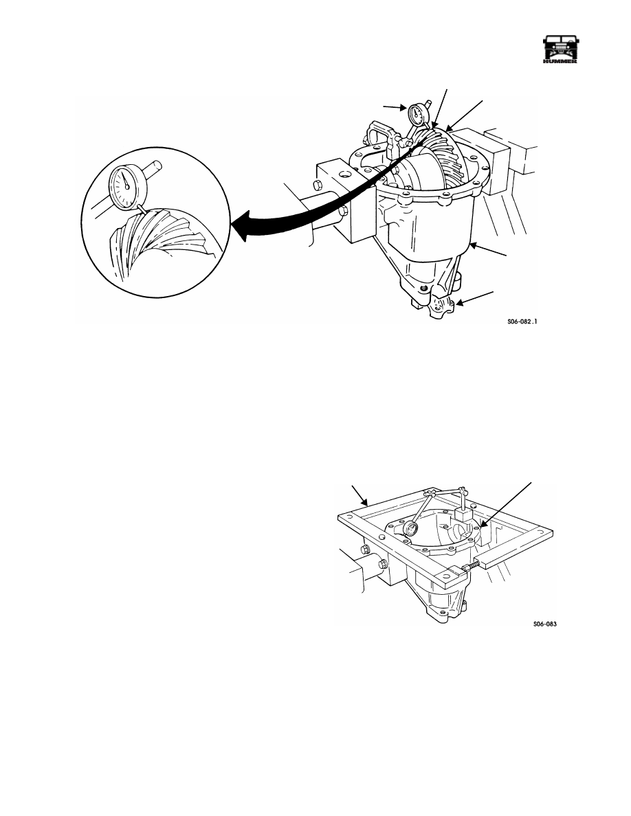
35. Mount dial indicator on housing and position indicator to
read off ring gear mounting surface of differential
assembly (Figure 9-94).
Figure 9-94: Dial Indicator Positioning For Case
Runout Check
36. Pry between differential assembly and bearing cap on one
side of indicator. Pry on opposite side to read end play.
37. Amount read on indicator is shim thickness that should be
added to side bearing shims to arrive at zero end play. Add
necessary shims and repeat procedure to ensure accuracy.
Figure 9-95: Ring Gear Guide Pin Installation
38. Tighten four bolts to 55-70 lb-ft (75-95 N•m).
39. Rotate differential assembly and check runout. Runout
should not exceed 0.002 in. (0.05 mm).
40. Remove dial indicator from housing.
NOTE:
Tag shims and bearing cups for assembly.
41. Remove four bolts, two bearing caps, bearing cups, shims,
and differential assembly from housing (Figure 9-96).
42. Install four guide pins in ring gear (Figure 9-95).
Figure 9-96: Differential Assembly Mounting
43. Support ring gear with wood blocks in press.
44. Press differential assembly on ring gear.
45. Remove four guide pins from ring gear.
46. Install ring gear on differential assembly with eight bolts.
Tighten bolts to 95-115 lb-ft (129-156 N•m).
47. Install side bearing shims, previously selected to remove
differential assembly side play, slide bearing cups, and
differential assembly in housing (Figure 9-96).
48. Install two bearing caps in housing with four bolts.
Tighten bolts to 55-70 lb-ft (75-95 N•m).
49. Attach dial indicator to housing and position indicator to
read off drive side of ring gear tooth at a right angle
(Figure 9-97).
RING GEAR
FLANGE OF CASE
DIAL INDICATOR
DIFFERENTIAL
CASE
RING GEAR
GUIDE PIN
BEARING
BEARING
DIFFERENTIAL
BEARING
BEARING
BEARING SHIM
HOUSING
CUP
SHIM
CAP
ASSEMBLY
CUP
9-38
Axles, Suspension, and Frame
_________________________________________
®
Figure 9-97: Checking Ring Gear Backlash
NOTE:
Backlash must be checked at four equally spaced
points on ring gear and must not vary more than 0.002 in. (0.05
mm) between four points checked.
50. Move ring gear back and forth while holding pinion yoke
stationary. Note backlash registered on indicator.
51. Ring gear backlash should be 0.005-0.009 in. (0.13-0.23
mm) with 0.008 in. (0.20 mm) desired. If backlash must be
adjusted perform steps 52 through 55, if not go to step 56.
NOTE:
Tag shims and bearing cups for assembly.
52. Remove four bolts, two bearing caps, bearing cups, shims,
and differential assembly from housing (Figure 9-96).
NOTE:
The following example will explain the procedure for
adjusting backlash: If side play was removed using 0.090 in.
(2.29 mm) shims on each side totaling 0.180 in. (4.57 mm) and
backlash, when checked, is found to be 0.011 in. (0.28 mm),
add 0.004 in. (0.10 mm) to shim on ring gear side and subtract
0.004 in. (0.10 mm) from shim on opposite side to correct
backlash. This will result in 0.094 in. (2.39 mm) shim on ring
gear side and 0.086 in. (2.18 mm) shim on other side. Backlash
will be approximately 0.007-0.008 in. (0.18 to 0.20 mm). Total
Shim Thickness remains 0.180 in. (4.57 mm).
53. To increase backlash, install thinner shim on ring gear side
and thicker shim on opposite side. To decrease backlash,
install thicker shim on ring gear side and thinner shim on
opposite side. Do not change total shim thickness.
54. Install shims, bearing cups, differential assembly, and
bearing caps in housing and secure with four bolts.
Tighten bolts to 55-70 lb-ft (75-95 N•m).
55. Mount dial indicator and recheck backlash. If necessary,
repeat steps 52 through 54.
56. Remove four bolts, bearing caps, bearing cup, shims, and
differential assembly from housing. Tag shims and
bearing cup for assembly.
57. Install axle housing spreader into holes in axle holding
fixture adapters and install dial indicator to read from each
end of housing. Indicator must have preload setting of
0.020 in. (0.50 mm) (Figure 9-98).
Figure 9-98: Axle Housing Spreader Mounting
CAUTION: Over-spreading of axle housing will damage
housing.
58. Spread housing 0.010 in. (0.25 mm) and remove dial
indicator.
NOTE:
Differential bearings must be preloaded to compen-
sate for heat and loads during operation.
RING GEAR TOOTH
RING GEAR
HOUSING
PINION YOKE
DIAL INDICATOR J–8001
AXLE
HOUSING
SPREADER
AXLE HOLDING
FIXTURE ADAPTER
J–24385-01

________________________________________
Axles, Suspension, and Frame 9-39
®
05745159
59. Preload differential side bearings by increasing shim
thickness at each side of differential assembly by 0.004 in.
(0.10 mm) for a total bearing preload of 0.008 in. (0.20
mm) (Figure 9-96).
60. Lubricate side bearings with gear oil and install
differential assembly, bearing cups, shims, and bearing
caps in housing and secure with four bolts (Figure 9-96).
NOTE:
Preloaded differential bearings may change backlash
setting. Check and correct backlash if necessary.
61. Remove housing spreader and tighten bolts to 55-70 lb-ft
(75-95 N•m).
62. Apply silicone sealant to cover sealing surface and secure
cover to housing with twelve bolts. Tighten bolts to 16 lb-
ft (22 N•m) (Figure 9-99).
Figure 9-99: Housing Cover Installation
63. Remove housing from holding fixture.
64. Remove four bolts and two axle holding fixture adapters
from housing.
65. Using press, install output shaft bearings on output shafts
(Figure 9-100).
Figure 9-100: Bearing Installation
66. Using axle shaft and seal installer J–33142, install output
shaft assemblies into axle assembly (Figure 9-101).
Figure 9-101: Axle Shaft And Seal Installer Usage
67. Using axle shaft and seal installer J–33142, install output
shaft seals in axle assembly (Figure 9-102).
Figure 9-102: Output Shaft Seal Installation
68. Lubricate sealing surface on output flanges with
lubricating oil (Figure 9-103).
Figure 9-103: Output Shaft Seal Installation
69. Install two output flanges, two seals, and two locknuts on
output shafts. Finger tighten locknuts.
70. Install axle assembly.
COVER
HOUSING
OUTPUT SHAFT BEARING
OUTPUT SHAFT
AXLE ASSEMBLY
OUTPUT SHAFT
ASSEMBLY
AXLE SHAFT
AND SEAL
INSTALLER
J–33142
AXLE ASSEMBLY
OUTPUT
AXLE SHAFT AND
SEAL INSTALLER J–33142
SHAFT SEAL
OUTPUT
OUTPUT
FLANGE
SHAFT
RUBBER
WASHER
9-40
Axles, Suspension, and Frame
_________________________________________
®
FRONT PROPELLER SHAFT AND
U-JOINT SERVICE
Front Shaft Removal
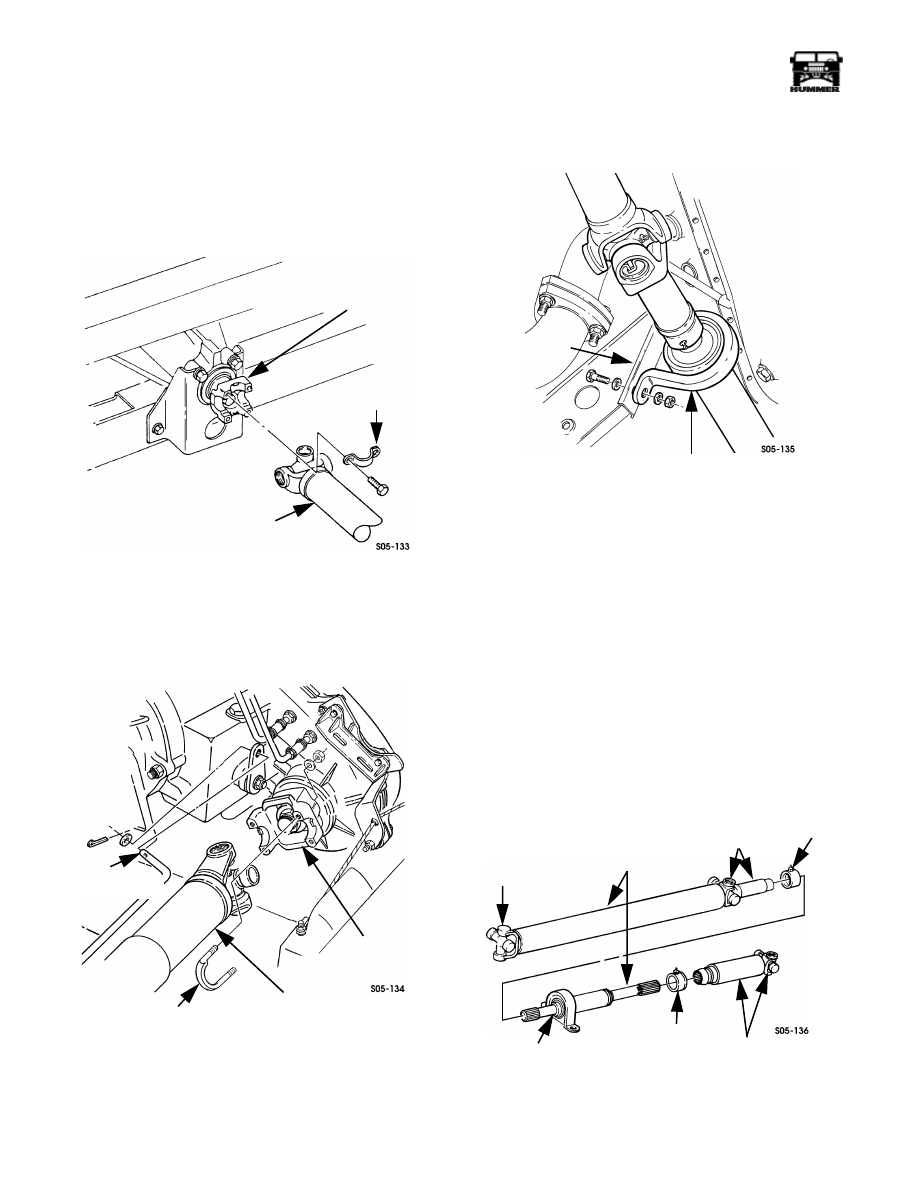
1.
Remove U-joint clamp bolts and straps. Then disconnect
shaft yoke (Figure 9-104).
Figure 9-104: Front Propeller Shaft
Attachment at Axle
2.
Remove U-bolt nuts and disconnect front shaft from
transfer case output yoke (Figure 9-105).
Figure 9-105: Front Propeller Shaft Attachment at
Transfer Case
3.
Disconnect transfer case shift rod at range lever.
4.
Remove bolts attaching center bearing to engine mount
(Figure 9-106).
Figure 9-106: Center Bearing Attachment
5.
Move front shaft forward, then rearward over top of
transfer case and remove from vehicle.
FRONT PROPELLER SHAFT DISASSEMBLY
AND OVERHAUL
1.
Mark slip yokes for assembly alignment.
2.
Mount shaft in vise and remove dust caps (Figure 9-107).
3.
Pull slip yokes off propshaft and separate shaft halves.
4.
Install standard bearing puller between center bearing and
shield.
5.
Mount assembly in shop press and press center bearing off
shaft.
6.
Remove shield from front propeller shaft.
Figure 9-107: Front Propeller Shaft Assembly
STRAP
FRONT
AXLE
YOKE
FRONT PROPELLER
SHAFT
TRANSFER CASE
OUTPUT YOKE
FRONT PROPELLER
U-BOLT
TRANSFER CASE
SHIFT ROD
SHAFT
CENTER BEARING
ENGINE MOUNT
U-JOINT
REAR SLIP YOKE
AND U-JOINT
DUST
CAP
FRONT
PROP
SHAFT
CENTER
BEARING
DUST
CAP
FRONT SLIP
YOKE AND
U-JOINT
Нет комментариевНе стесняйтесь поделиться с нами вашим ценным мнением.
Текст