Engines Iveco N45, N67. Manual — part 13
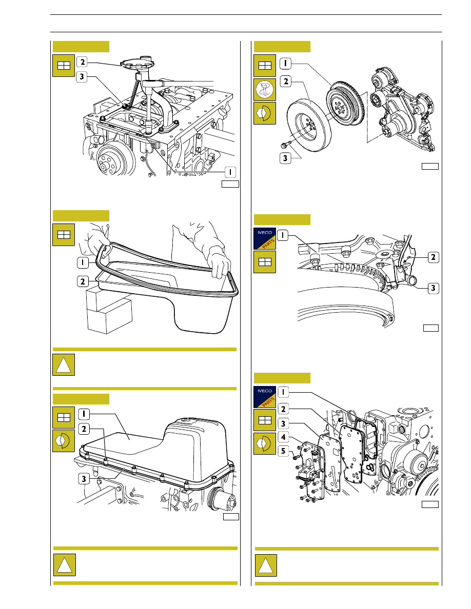
Figure 54
Fit the plate (1), the oil pick up tube (2) and tighten the
fastening screws (3) to the specified torque.
Figure 55
Set the gasket (1) on the oil sump (2).
!
The pictures of the instructions relating to the oil pan
and to thesuction rose may not reflect the actual shape
and dimensions of your engine equipment. However
the procedures described are still applicable.
Figure 56
Fit the oil sump (1) and apply the plate (3) to it.
Tighten the screws (2) to the specified torque.
74775
Figure 57
Assemble the pulley (1) and the damping flywheel (2) to the
driving shaft.
Tighten the fixing screws (3) and clamp them to the couple
68
± 7 Nm.
70230
Fit a new sealing ring on the speed sensor (3).
Fit the speed sensor (3) on the front cover (1) and tighten
the screw (2) to the specified torque.
Figure 58
Figure 59
Fit on the engine block: a new gasket (1), the heat exchanger
(2) a new gasket (3) and the oil filter support (4).
Tighten the screws (5) to the specified torque.
!
Before any assembly operation always verify that the
hole and screw threads have no evidence of wear or
dirt.
!
Before any assembly operation always verify that the
hole and screw threads have no evidence of wear or
dirt.
108553
108548
108576
SECTION 3 - DUTY-INDUSTRIAL APPLICATION
21
F4HE NEF ENGINES
Print P2D32N003GB
Base - February 2006
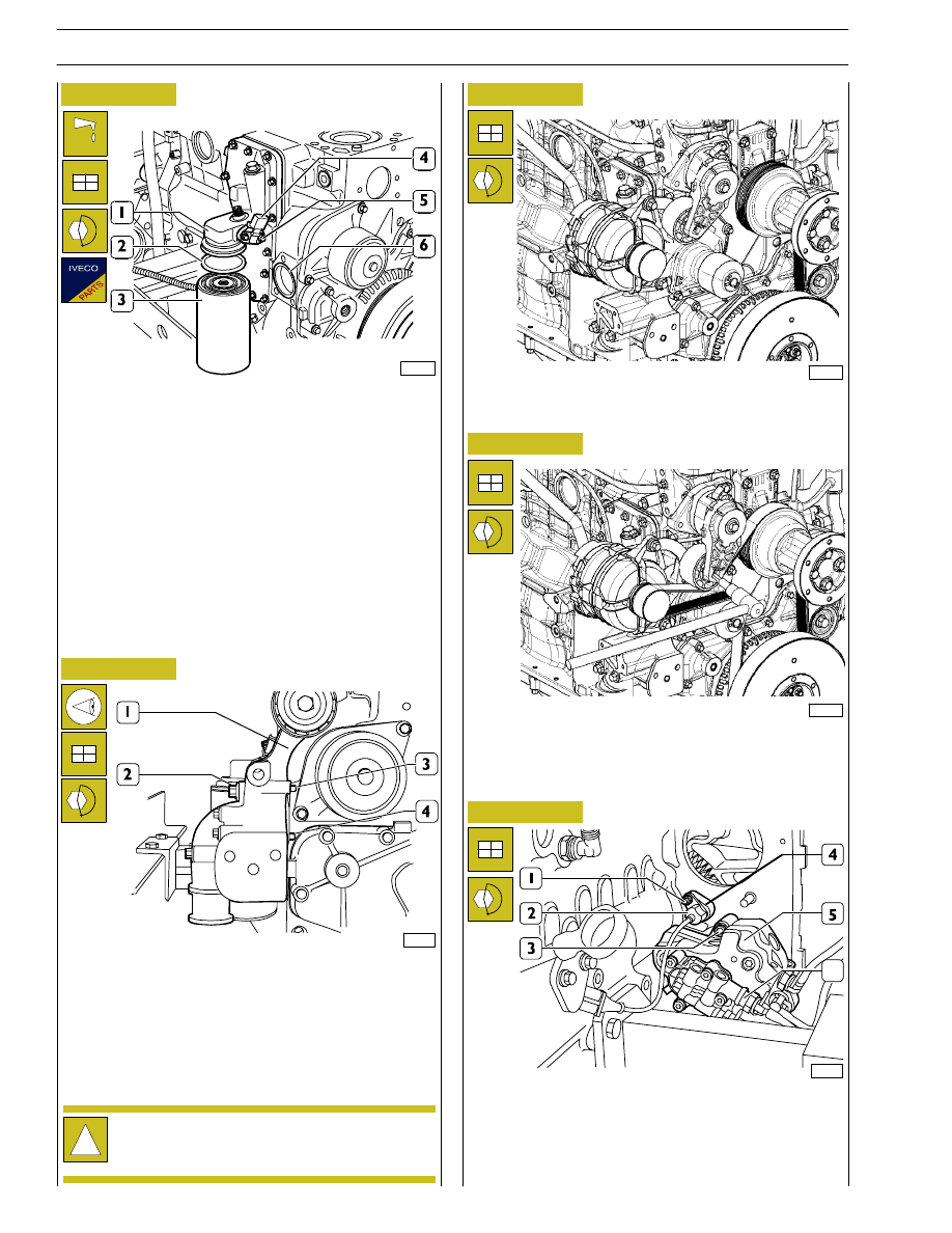
Figure 60
Figure 61
Lubricate the sealing ring (2) with engine oil and set it on the
oil filter (3).
Screw manually to seat the oil filter (3) on the support
connection (1) and then screw again the oil filter (3) by
¾
turn.
Apply a new sealing ring on the oil temperature/pressure
sensor (4) and fit it on the support (1).
Tighten the screws (5) to the specified torque.
Fit a new sealing ring (6) in the engine block seat.
70234
Position the alternator support (1) so that pins (3 and 4) are
set against the engine block.
Tighten the screws (2) to the specified torque.
Refit the alternator (1).
Tighten the screw (2) to the specified torque.
Figure 62
Figure 63
Refit the automatic belt tensioner (2).
Tighten the screw (3) to the specified torque using a wrench,
turn the automatic belt tensioner (2) to fit the belt (1) on
pulleys and guide rollers.
70145
Refit the high pressure pump (6) including the feed pump (5)
and tighten the nuts (3) to the specified torque. Fit the
support (4) with a new sealing ring, the timing sensor (2) with
a new sealing ring and tighten the relevant fastening nut (1)
to the specified torque.
Figure 64
!
Before any assembly operation always verify that the
hole and screw threads have no evidence of wear or
dirt.
108578
108550
108552
22
SECTION 3 - DUTY-INDUSTRIAL APPLICATION
F4HE NEF ENGINES
Base - February 2006
Print P2D32N00GB

Figure 65
Insert the power take-off (2) equipped with the gasket (4),
the cover (I) and its gasket (4).
Tighten the screws (3) to the prescribed matching couple.
74176
Figure 66
Assemble the electronic gearbox (2) equipped with the
exchanger to the engine, fixing it with the screws (1).
In case the rubber buffers are cracked or excessively
deformed, provide replacing them.
74174
Figure 67
Direct the output shaft (4) and the camshaft (2) so that when
fitting the driven gear (1) on the camshaft the marks on the
gears (1 and 3) are coinciding.
Figure 68
Assemble cylinder head (1), tighten the screws (2) in three
following steps, following order and mode shown in the
figure below.
!
The angle tightening is carried out through tool
99395216 (3).
α
70336
Tightening order layout for cylinder head fastening screws:
- 1
st
step pre-tightening with dynamometric wrench:
• Screw 12x1.75x130 ( ) 35
± 5 Nm
• Screw 12x1.75 x 150 ( ) 55
± 5 Nm
- 2
nd
step tightening with a 90
± 5° angle
- 3
rd
step tightening with a 90
± 5° angle
A = Front side
70476
α
Figure 69
A
74779
1
2
3
4
1
2
6-cylinder engine
!
Before any assembly operation always verify that the
hole and screw threads have no evidence of wear or
dirt.
SECTION 3 - DUTY-INDUSTRIAL APPLICATION
23
F4HE NEF ENGINES
Print P2D32N003GB
Base - February 2006

Figure 70
Figure 71
70338
Fit a new sealing ring (2) lubricated with petroleum jelly and
a new sealing washer (3) on injector (1).
70339
Fit injectors (1) on the cylinder head seats, directed so that
the fuel inlet hole (2) is facing the fuel manifold seat (3) side.
Figure 72
70133
Use tool 99342101 (1) to fit the injector (2) into its seat.
Screw injector fastening screws without tightening them.
Figure 73
70337
4-cylinder engine
A
α
Cylinder head fastening screws tightening sequence:
- 1
st
stage pre-tightening, with a torque wrench::
• Screw 12x1.75x130 ( ) 35
± 5 Nm
• Screw12x1.75 x 150 ( ) 55
± 5 Nm
A = Lato anteriore
- 2
nd
stage tightening with angle 90
± 5°
- 3
rd
stage tightening with angle 90
± 5°
24
SECTION 3 - DUTY-INDUSTRIAL APPLICATION
F4HE NEF ENGINES
Base - February 2006
Print P2D32N00GB
Нет комментариевНе стесняйтесь поделиться с нами вашим ценным мнением.
Текст