DAF LF45, LF55 Series. Manual — part 258

©
200508
4-3
Removal and installation
ALLISON 1000 & 2000 AUTOMATIC GEARBOXES
ΛΦ45/55 series
3
7
4.2 REMOVING AND INSTALLING SELECTOR SWITCH
Removing selector switch
1.
Remove the selector cable from the selector
arm.
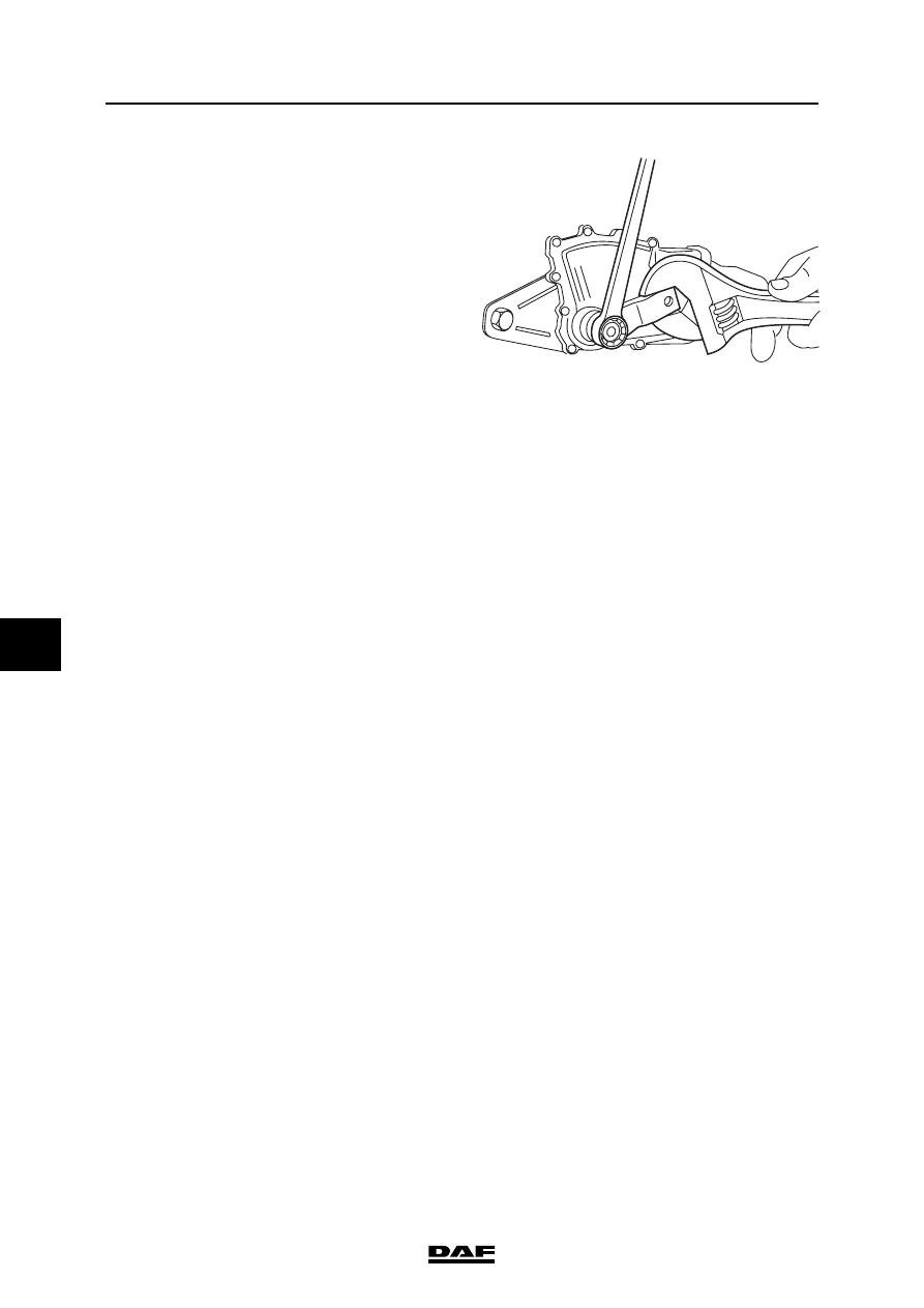
2.
Remove the attachment nut from the
selector shaft.
The selector shaft must not be
turned while the attachment nut is
being loosened or tightened. While
loosening or tightening the
attachment nut, lock the selector
shaft using the selector arm and an
appropriate tool.
3.
Remove the selector arm.
4.
Remove the connectors from the selector
switch.
5.
Take the attachment bolts out of the selector
switch and remove it.
Fitting selector switch
1.
Put the selector shaft in the neutral position.
See the marks on the gearbox housing.
2.
Put the selector switch in the neutral position
using special tool (DAF no. 1451992).
3.
Fit the selector switch, together with the
special tool, over the selector shaft and onto
the gearbox housing.
4.
Install the selector switch attachment bolts
and tighten them to the specified torque. See
"Technical data".
5.
Fit the selector arm onto the selector shaft
and tighten the attachment nut to the
specified torque. See "Technical data".
V3 00 482
}
V3 00 481
ALLISON 1000 & 2000 AUTOMATIC GEARBOXES
4-4
©
200508
Removal and installation
7
ΛΦ45/55 series
3
The selector shaft must not be
turned while the attachment nut is
being loosened or tightened. While
loosening or tightening the
attachment nut, lock the selector
shaft using the selector arm and an
appropriate tool.
6.
Fit the selector cable into the selector arm.
Note:
The attachment of the selector cable must be
fitted so that the connecting pin can move
freely in every gear.
V3 00 482
}
©
200508
4-5
Removal and installation
ALLISON 1000 & 2000 AUTOMATIC GEARBOXES
ΛΦ45/55 series
3
7
4.3 REMOVING AND INSTALLING OUTPUT SHAFT OIL SEAL
Removing output shaft oil seal
1.
Chock the wheels so that the vehicle cannot
roll.
2.
Loosen the prop shaft and hang the shaft so
that it does not interfere with the operations.
3.
Take the attachment bolt out of the drive
flange and remove the drive flange.
4.
Drill two holes in the external cover of the oil
seal and turn special tool (DAF no. 0484899)
into the oil seal. Pull the oil seal out of the
gearbox housing using special tool
(DAF no. 0694928).
Installing output shaft oil seal
1.
Fit the new oil seal as far as possible into the
gearbox housing using special tool
(DAF no. 1240037).
2.
Check the prop shaft at the level of the oil
seal for irregularities and wear.
Note:
Slight irregularities can be smoothed using
fine sandpaper.
3.
Lightly lubricate the prop shaft at the level of
the oil seal with clean gearbox oil.
4.
Fit the prop shaft and tighten the attachment
bolt to the specified torque. See "Technical
data".
ALLISON 1000 & 2000 AUTOMATIC GEARBOXES
4-6
©
200508
Removal and installation
7
ΛΦ45/55 series
3
4.4 REMOVING AND FITTING SELECTOR SHAFT OIL SEAL
Removing selector shaft oil seal
1.
Put the gearbox selector lever in the neutral
position.
2.
Remove the selector cable from the selector
switch.
3.
Remove the attachment nut from the
selector shaft.
The selector shaft must not be
turned while the attachment nut is
being loosened or tightened. While
loosening or tightening the
attachment nut, lock the selector
shaft using the selector arm and an
appropriate tool.
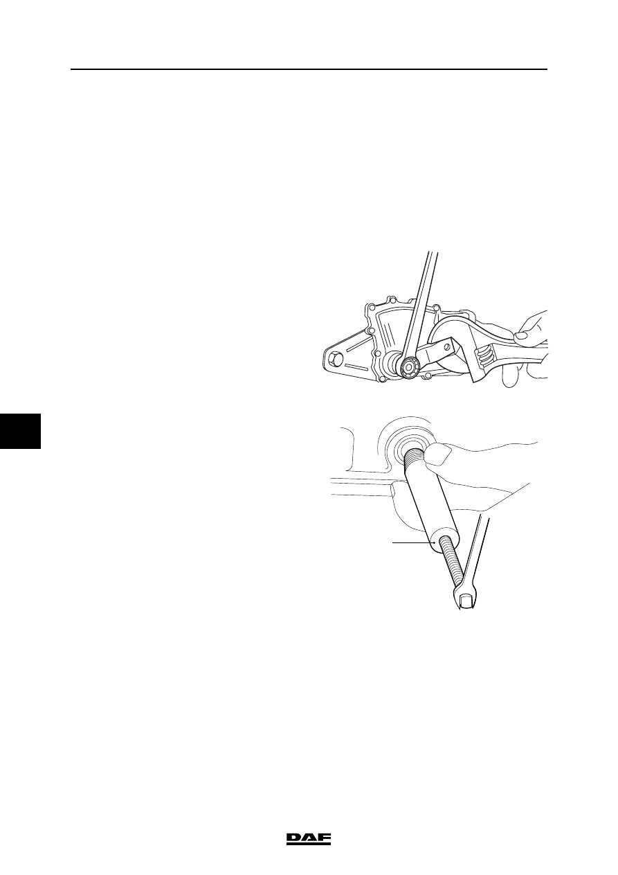
4.
Remove the selector switch.
5.
Fit special tool (DAF no. 1453124) over the
selector shaft and turn it into the oil seal.
6.
Tighten the nut on the special tool (2) and
remove the oil seal from the selector shaft
bush.
7.
Check the selector shaft bush and the
selector shaft for irregularities and wear.
Note:
Slight irregularities can be smoothed using
fine sandpaper.
V3 00 482
}
2
V3 00 560
Нет комментариевНе стесняйтесь поделиться с нами вашим ценным мнением.
Текст