Dodge Dakota (ND). Manual — part 1214
WARNING: On vehicles equipped with the occupant classification system (ocs) do not hang any after mar-
ket devices from the front passengers seat back. Do not install a front drivers seat back cover with map
pocket onto the passenger seat. Failure to follow these instructions may result in personal injury or death.
WARNING: The Seat Weight Sensor is a sensitive, calibrated unit and must be handled carefully. Do not
drop or handle roughly. If dropped or damaged, replace with another sensor. Failure to follow these instruc-
tions may result in personal injury or death.
WARNING: The front passenger seat must be handled carefully as well. When removing the seat, be careful
when setting on floor not to drop. If dropped, the sensor may be inoperative. Failure to follow these instruc-
tions may result in personal injury or death.
WARNING: When the seat is on the floor, no one should sit in the front passenger seat. This uneven force
may damage the sensing ability of the seat weight sensors. If sat on and damaged, the sensor may be
inoperative. Failure to follow these instructions may result in personal injury or death.
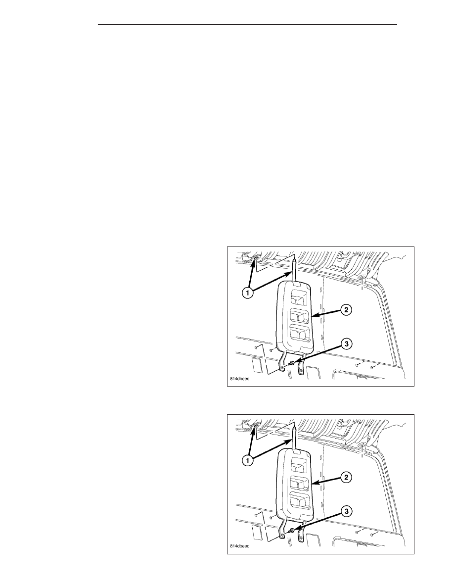
HEADREST-CLUB CAB
REMOVAL
1. Disconnect and isolate the battery negative cable.
2. Remove the cab back trim panel (Refer to 23 -
BODY/INTERIOR/REAR CAB BACK PANEL TRIM
- REMOVAL).
3. Remove the fasteners (3) securing the lower head-
rest to the cab back.
4. Lower the headrest (2) to disengage the upper post
from the grommet (1).
5. Remove the headrest from the vehicle.
INSTALLATION
1. Position the headrest (2) into the vehicle.
2. Insert the upper post into the grommet (1) and
push up slightly on the headrest (2).
3. Install the fasteners (3) to secure the lower head-
rest to the cab back.
4. Tighten the fasteners to 12 N·m (9 ft. lbs.).
5. Install the cab back trim panel (Refer to 23 -
BODY/INTERIOR/REAR CAB BACK PANEL TRIM
- INSTALLATION).
6. Connect the battery negative cable.
23 - 268
SEATS
ND

SEAT-FRONT
REMOVAL
1. Before proceeding with the following repair proce-
dure, review all warnings and cautions. (Refer to
23 - BODY/SEATS - WARNING)
WARNING: The Seat Weight Sensor is a sensitive,
calibrated unit and must be handled carefully. Do
not drop or handle roughly. If dropped or dam-
aged, replace with another sensor. Failure to fol-
low these instructions may result in personal
injury or death.
WARNING: The front passenger seat must be han-
dled carefully as well. When removing the seat, be
careful when setting on floor not to drop. If
dropped, the sensor may be inoperative. Failure to
follow these instructions may result in personal
injury or death.
WARNING: When the seat is on the floor, no one
should sit in the front passenger seat. This uneven force may damage the sensing ability of the seat weight
sensors. If sat on and damaged, the sensor may be inoperative. Failure to follow these instructions may
result in personal injury or death.
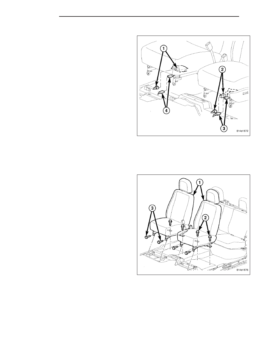
2. Move the seat forward to gain access to the rear (2) bolts.
3. Disconnect and isolate the battery negative cable.
4. Remove the cover and lower seat belt anchor.
5. Remove the front (3) and rear (2) bolts.
6. Disconnect the electrical connectors, if equipped,
and remove the seat from the vehicle.
ND
SEATS
23 - 269
INSTALLATION
1. Before proceeding with the following repair proce-
dure, review all warnings and cautions. (Refer to
23 - BODY/SEATS - WARNING)
WARNING: The Seat Weight Sensor is a sensitive,
calibrated unit and must be handled carefully. Do
not drop or handle roughly. If dropped or dam-
aged, replace with another sensor. Failure to fol-
low these instructions may result in personal
injury or death.
WARNING: The front passenger seat must be han-
dled carefully as well. When removing the seat, be
careful when setting on floor not to drop. If
dropped, the sensor may be inoperative. Failure to
follow these instructions may result in personal
injury or death.
WARNING: When the seat is on the floor, no one
should sit in the front passenger seat. This uneven force may damage the sensing ability of the seat weight
sensors. If sat on and damaged, the sensor may be inoperative. Failure to follow these instructions may
result in personal injury or death.
2. Position the seat into the vehicle and connect the electrical connectors, if equipped.
3. Install the front bolts (3) and rear bolts (2).
4. Tighten the front inner bolt to 27 N·m (20 ft. lbs.)
then tighten the front outer bolt to 27 N·m (20 ft.
lbs.).
5. Tighten the rear bolts to 47 N·m (35 ft. lbs.).
6. Install the lower seat belt anchor and install the
bolt.
7. Tighten the bolt to 39 N·m (29 ft. lbs.) and install
the trim cover.
8. Do not reconnect the battery negative cable at this
time. The supplemental restraint system verification
test procedure should be performed following ser-
vice of any supplemental restraint system compo-
nent. (Refer to 8 - ELECTRICAL/RESTRAINTS -
STANDARD
PROCEDURE
-
VERIFICATION
TEST).
9. Following successful completion of the supplemen-
tal restraint system verification test procedure, per-
form
the
Occupant
Classification
System
Verification Test using a scan tool. (Refer to 8 - ELECTRICAL/RESTRAINTS - *OCS VERIFICATION TEST -
VER 1)
23 - 270
SEATS
ND
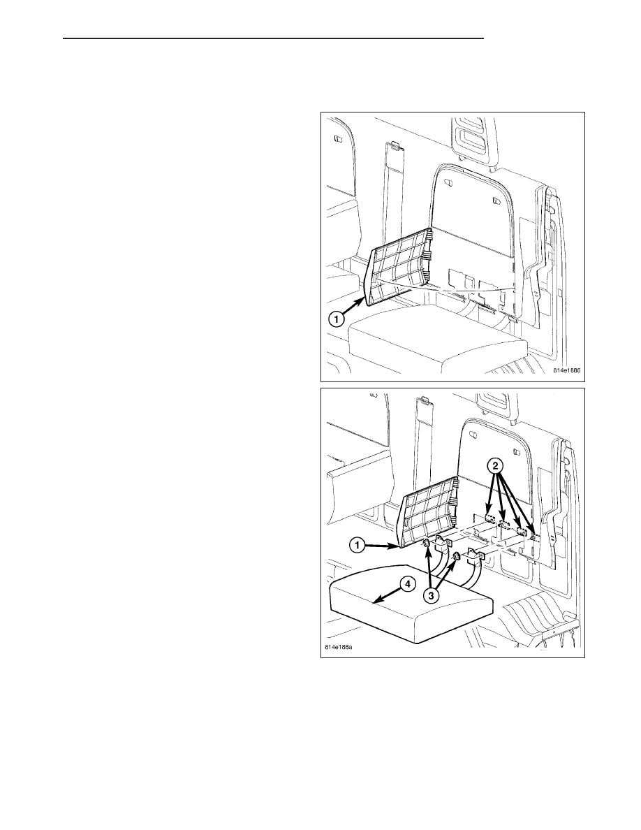
SEAT-CLUB CAB
REMOVAL
NOTE: The seat back is part of the cab back trim
panel. (Refer to 23 - BODY/INTERIOR/REAR CAB
BACK PANEL TRIM - REMOVAL) for the appropri-
ate removal procedure.
1. Remove the cab back trim panel (Refer to 23 -
BODY/INTERIOR/REAR CAB BACK PANEL TRIM
- REMOVAL).
2. Remove the fasteners (3) attaching rear seat cush-
ion hinge to cab back panel (2).
3. Separate rear seat cushion (4) from vehicle.
ND
SEATS
23 - 271
Нет комментариевНе стесняйтесь поделиться с нами вашим ценным мнением.
Текст