Chrysler Le Baron, Dodge Dynasty, Plymouth Acclaim. Manual — part 175
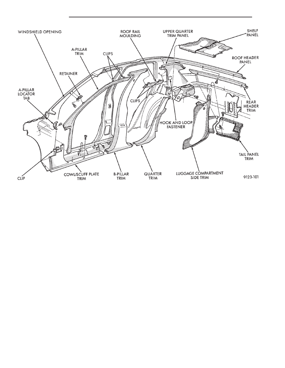
(4) Remove screws holding rear header moulding
to roof as necessary to clear quarter removal path.
(5) Remove screws holding upper quarter trim
panel to quarter panel.
(6) Disengage hook and loop fastener holding trim
to quarter panel.
(7) Pull trim panel forward and separate from ve-
hicle.
INSTALLATION
Reverse the preceding operation.
FRONT SEAT BELTS—AP-44 BODY
FRONT SHOULDER HARNESS/LAP BELT
REMOVAL (FIG. 32)
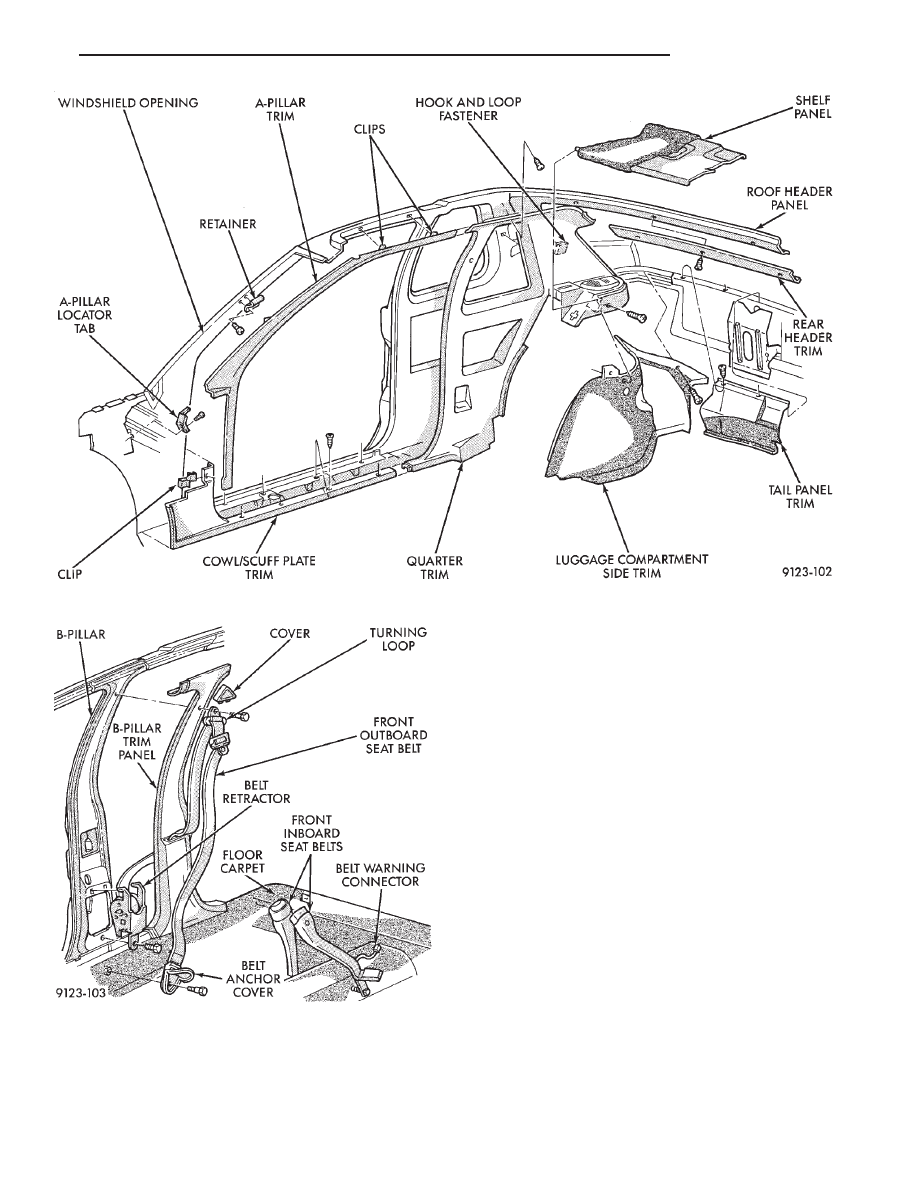
(1) Remove B-pillar trim panel.
(2) Remove bolt holding seat belt retractor to
B-pillar.
(3) Separate retractor from vehicle.
FRONT SHOULDER HARNESS/LAP BELT
INSTALLATION
Reverse the preceding operation.
FRONT INBOARD BUCKLE REMOVAL (FIG. 32)
(1) Remove bolt holding inboard buckle to floor.
(2) Disconnect seat belt sensor wire connector.
(3) Separate buckle assembly from vehicle.
FRONT INBOARD BUCKLE INSTALLATION
Reverse the preceding operation.
FRONT SEAT BELTS—AP-24 BODY
FRONT SHOULDER HARNESS/LAP BELT
REMOVAL (FIG. 33)
(1) Remove quarter trim panel as necessary.
(2) Remove bolt holding seat belt retractor quarter
panel.
(3) Remove bolt holding front lap belt anchor to
floor.
(4) Separate retractor from vehicle.
FRONT SHOULDER HARNESS/LAP BELT
INSTALLATION
Reverse the preceding operation.
FRONT INBOARD BUCKLE REMOVAL (FIG. 33)
(1) Remove bolt holding inboard buckle to floor.
(2) Disconnect seat belt sensor wire connector.
(3) Separate buckle assembly from vehicle.
FRONT INBOARD BUCKLE INSTALLATION
Reverse the preceding operation.
Fig. 30 Interior Mouldings, Panels, and Trim Covers—AP-44 Body
23 - 110
AP-BODY
Ä
REAR SEAT BELTS
REAR SHOULDER HARNESS/LAP BELT
REMOVAL (FIG. 34)
(1) Remove rear shoulder harness turning loop
cover. Remove bolt holding turning loop to roof
panel.
(2) Remove quarter trim panel, lower panel on AP-
44.
(3) Remove bolt holding lap belt to floor at wheel-
house kickup.
(4) Remove bolt holding seat belt retractor to quar-
ter panel.
REAR SHOULDER HARNESS/LAP BELT
INSTALLATION
Reverse the preceding operation.
REAR INBOARD BUCKLE/CENTER OCCUPANT
BELTS REMOVAL (FIG. 34)
(1) Remove rear seat cushion.
(2) Remove bolt holding inboard buckle/center oc-
cupant belt to floor.
(3) Separate buckle/belt assembly from vehicle.
REAR INBOARD BUCKLE/CENTER OCCUPANT
BELT INSTALLATION
Reverse the preceding operation.
FRONT SEATS
REMOVAL (FIG. 35 OR 36)
(1) Position seat full forward.
Fig. 31 Interior Mouldings, Panels, and Trim Covers—AP-24 Body
Fig. 32 Front Seat Belts—AP-44 Body
Ä
AP-BODY
23 - 111
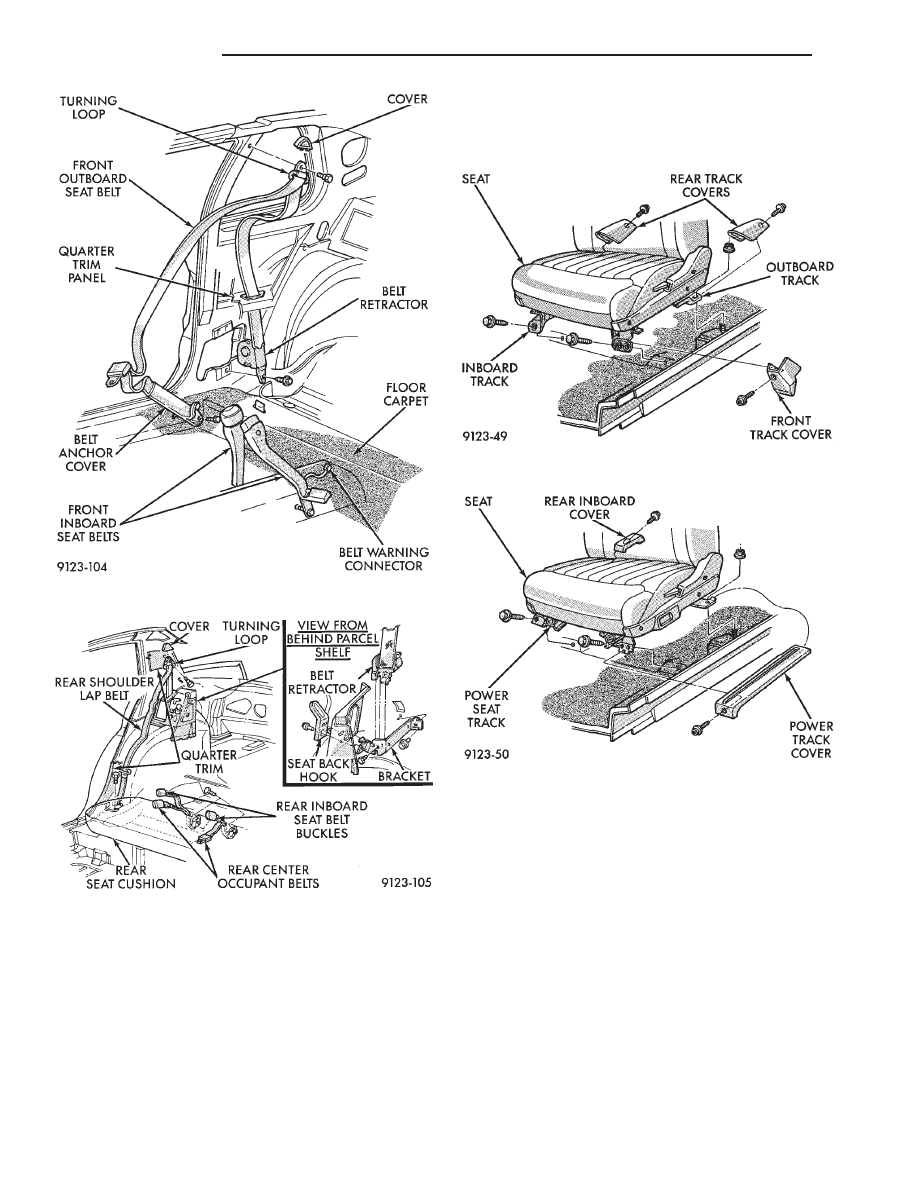
(2) Remove screws holding rear track riser covers
and separate covers from tracks.
(3) On power seat track, remove outboard track
cover.
(4) Remove nuts holding seat track to floor.
(5) Position seat full rearward.
(6) On power seat track, remove door sill scuff
plate and disconnect wire connector.
(7) Remove bolts holding seat track to cross mem-
ber.
(8) Remove seat from vehicle.
INSTALLATION
Reverse the preceding operation.
REAR SEATS
REAR SEAT CUSHION REMOVAL
(1) Remove bolts holding cushion to floor.
(2) Push center occupant seat belts through open-
ings in cushion.
(3) Remove cushion from vehicle.
REAR SEAT CUSHION INSTALLATION
Reverse the preceding operation.
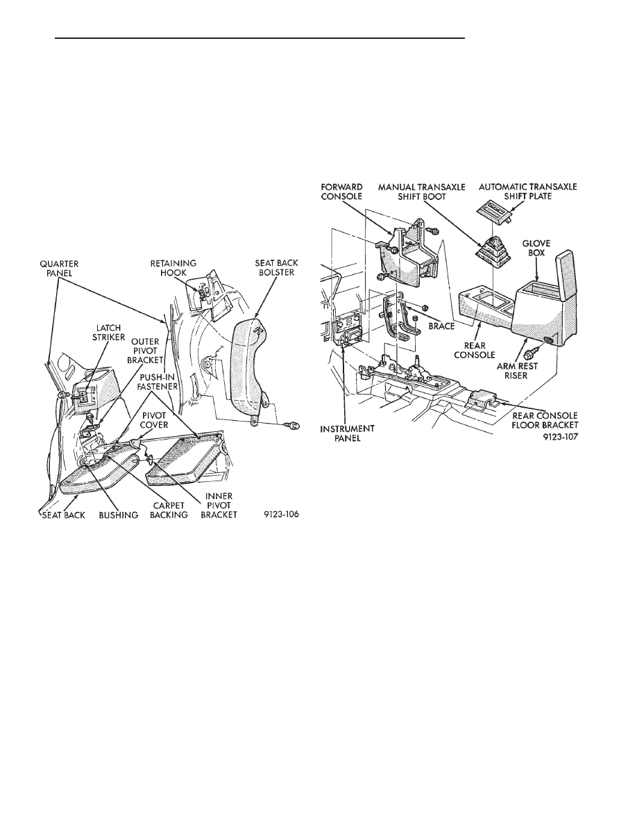
REAR SEAT BACK REMOVAL (FIG. 37)
(1) Hinge seat back forward and disengage push-in
fasteners holding carpet backing to trunk floor.
(2) Remove bolts holding outboard hinge pivot
bracket to seat back.
(3) Pull seat back outward to disengage inboard
pivot and separate from vehicle.
Fig. 33 Front Seat Belts—AP-24 Body
Fig. 34 Rear Seat Belts—Typical
Fig. 35 Manual Front Seat
Fig. 36 Power Front Seat
23 - 112
AP-BODY
Ä
REAR SEAT BACK INSTALLATION
Reverse the preceding operation.
SEAT BACK BOLSTER CUSHION REMOVAL
(FIG. 37)
(1) Remove rear seat cushion and back as neces-
sary.
(2) Remove bolts holding outboard seat back bol-
ster to quarter panel.
(3) Lift bolster upward to disengage hook retainer
on back of bolster and separate from vehicle.
SEAT BACK BOLSTER CUSHION
INSTALLATION
Reverse the preceding operation
FRONT CENTER CONSOLE
REMOVAL (FIG. 38)
(1) Position front seats full forward.
(2) Remove gear selector knob and PRNDL on ve-
hicles with automatic transaxle. Remove illumina-
tion lamp socket and position socket out of the way.
(3) Lift gear shift boot adapter from console and
push adapter through opening in console on vehicles
with manual transaxle.
(4) Remove bolts holding arm rest riser to floor
bracket.
(5) Separate rear console from floor and remove
from vehicle.
(6) Position front seats full rearward.
(7) Remove radio bezel from instrument panel. Re-
fer to Group 8E, Instrument Panel. Remove screws
holding console to instrument panel.
(8) Remove screws holding forward console to
lower instrument panel rail.
(9) Remove screws holding forward console to for-
ward brace.
(10) Separate forward console from vehicle.
INSTALLATION
Reverse the preceding operation. Verify PRNDL
adjustment before returning vehicle to use.
FLOOR CARPET
REMOVAL (FIG. 39)
(1) Remove cowl trim panels and scuff plates.
(2) Remove front seats and inboard seat belts.
(3) Remove center arm rest and front console.
(4) Remove outboard seat belt lower attaching
bolts.
(5) Remove rear seat cushion.
(6) Pull carpet from under B-pillar trim covers.
(7) Fold carpet and remove through front door
opening.
INSTALLATION
Reverse the preceding operation.
OVERHEAD CONSOLE
REMOVAL (FIG. 40)
(1) Remove screws holding overhead console to re-
inforcement bracket.
(2) Slide overhead console rearward to separate re-
inforcement bracket retainer tab from console.
(3) Lower console from roof and disconnect wire
connectors.
Fig. 37 Rear Seat Back and Bolster
Fig. 38 Front Center Console
Ä
AP-BODY
23 - 113
Нет комментариевНе стесняйтесь поделиться с нами вашим ценным мнением.
Текст