Infiniti FX35 / FX45. Manual — part 678
CYLINDER HEAD
EM-229
< SERVICE INFORMATION >
[VK45DE]
C
D
E
F
G
H
I
J
K
L
M
A
EM
N
P
O
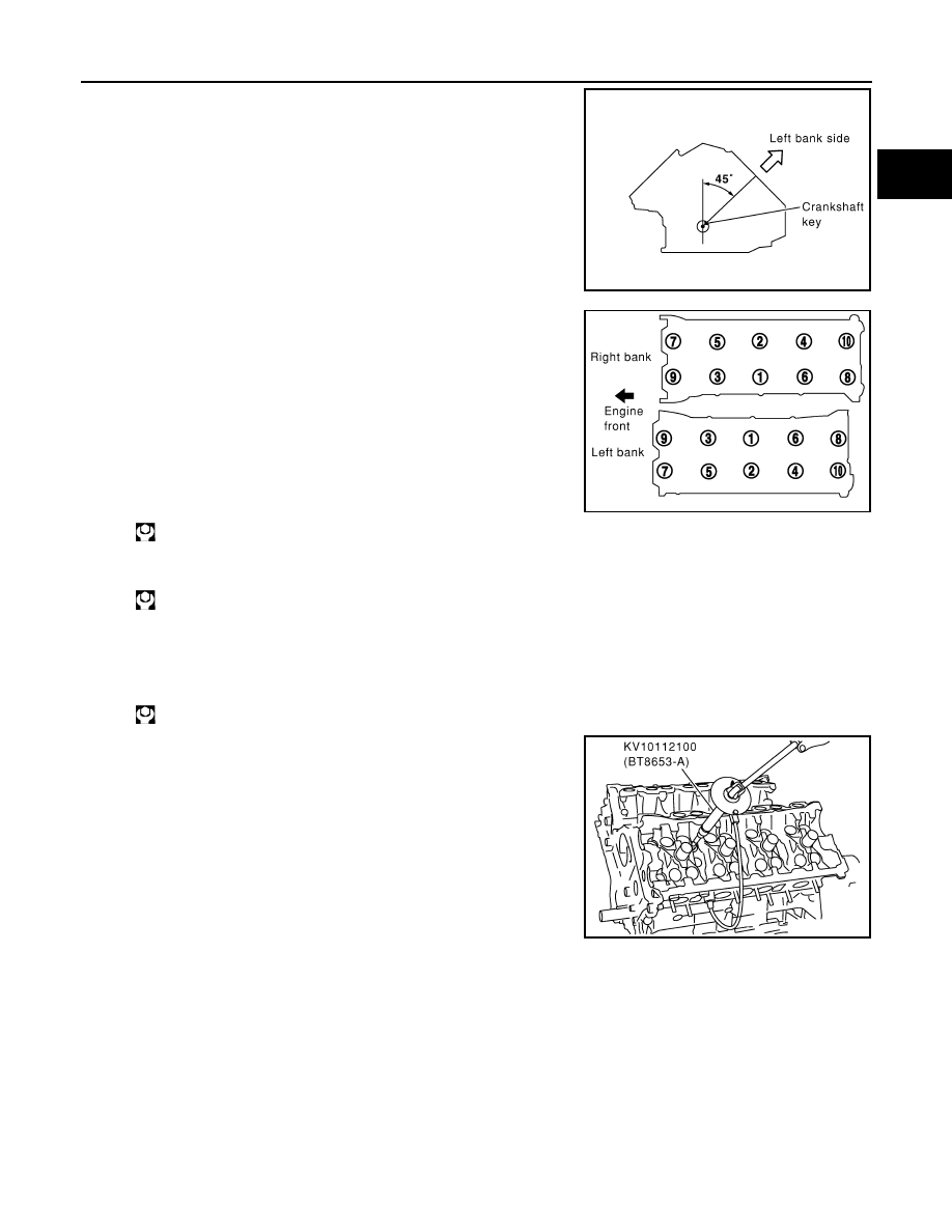
• Crankshaft key should line up with the left bank cylinder center
line as shown in the figure.
3.
Install cylinder head follow the steps below to tighten cylinder
head bolts in numerical order as shown in the figure with cylin-
der head bolt wrench (commercial service tool).
CAUTION:
If cylinder head bolts are re-used, check their outer diame-
ters before installation. Refer to "Cylinder Head Bolts Outer
Diameter".
a.
Apply new engine oil to threads and seating surface of cylinder
head bolts.
b.
Tighten all cylinder head bolts.
c.
Completely loosen all cylinder head bolts.
CAUTION:
In step “c”, loosen cylinder head bolts in reverse order of that indicated in the figure.
d.
Tighten all cylinder head bolts.
e.
Turn all cylinder head bolts 60 degrees clockwise. (Angle tight-
ening)
CAUTION:
Check the tightening angle by using angle wrench (SST).
Avoid judgment by visual inspection without SST.
• Check tightening angle indicated on angle wrench indicator
plate.
f.
Turn all cylinder head bolts 60 degrees clockwise again. (Angle
tightening)
4.
Install in the reverse order of removal.
Disassembly and Assembly
INFOID:0000000001325799
COMPONENTS
PBIC2389E
: 98.1 N·m (10 kg-m, 72 ft-lb)
: 0 N·m (0 kg-m, 0 ft-lb)
: 44 N·m (4.5 kg-m, 32 ft-lb)
PBIC0068E
PBIC0069E

EM-230
< SERVICE INFORMATION >
[VK45DE]
CYLINDER HEAD
• Refer to
for symbols in the figure.
DISASSEMBLY
1.
Remove spark plug with spark plug wrench (commercial service tool).
2.
Remove valve lifter.
• Identify installation positions, and store them without mixing them up.
3.
Remove valve collet.
• Compress valve spring with valve spring compressor, attach-
ment and adapter (SST). Remove valve collet with magnetic
hand.
CAUTION:
When working, take care not to damage valve lifter holes.
4.
Remove valve spring retainer and valve spring (with valve spring seat).
CAUTION:
Do not remove valve spring seat from valve spring.
5.
Push valve stem to combustion chamber side, and remove valve.
• Identify installation positions, and store them without mixing them up.
PBIC5277E
1.
Spark plug
2.
Valve lifter
3.
Valve collet
4.
Valve spring retainer
5.
Valve spring (with valve spring seat)
6.
Valve oil seal
7.
Valve guide
8.
Cylinder head (right bank)
9.
Valve seat
10.
Valve (INT)
11.
Valve (EXH)
12.
Cylinder head (left bank)
13.
Spark plug tube
: Apply genuine High Strength Lock-
ing Sealant or equivalent
PBIC2360E
CYLINDER HEAD
EM-231
< SERVICE INFORMATION >
[VK45DE]
C
D
E
F
G
H
I
J
K
L
M
A
EM
N
P
O
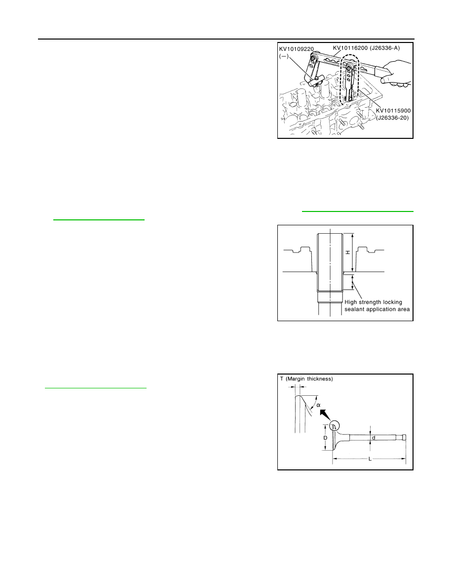
6.
Remove valve oil seal with valve oil seal puller (SST).
7.
If valve seat must be replaced, refer to
EM-232, "Inspection After Disassembly"
.
8.
If valve guide must be replaced, refer to
EM-232, "Inspection After Disassembly"
.
9.
Remove spark plug tube, as necessary.
• Using pair of pliers, pull spark plug tube out of cylinder head.
CAUTION:
• Take care not to damage cylinder head.
• Once removed, spark plug tube will be deformed and cannot be reused. Do not remove it unless
absolutely necessary.
ASSEMBLY
1.
When valve guide is removed, install it. Refer to
EM-232, "Inspection After Disassembly"
2.
When valve seat is removed, install it. Refer to
EM-232, "Inspection After Disassembly"
3.
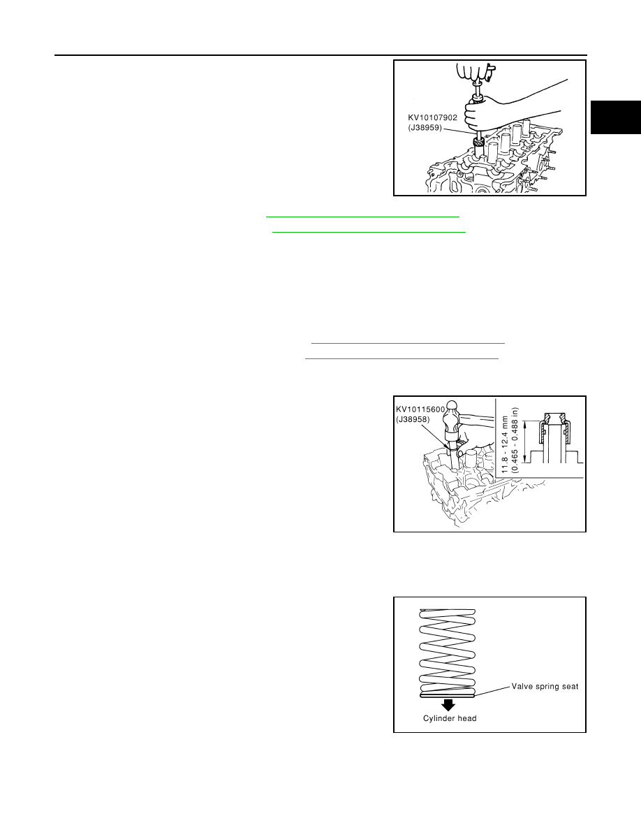
Install new valve oil seal as follows:
a.
Apply new engine oil on valve oil seal joint and seal lip.
b.
Install with valve oil seal drift (SST) to match dimension in the
figure.
4.
Install valve.
• Install in the original position.
NOTE:
Larger diameter valves are for intake side.
5.
Install valve spring (with valve spring seat).
• Install smaller pitch (valve spring seat side) to cylinder head
side.
6.
Install valve spring retainer.
7.
Install valve collet.
PBIC0072E
PBIC0073E
PBIC0074E
EM-232
< SERVICE INFORMATION >
[VK45DE]
CYLINDER HEAD
• Compress valve spring with valve spring compressor, attach-
ment and adapter (SST). Install valve collet with magnetic
hand.
CAUTION:
When working, take care not to damage valve lifter holes.
• Tap stem edge lightly with plastic hammer after installation to
check its installed condition.
8.
Install valve lifter.
• Install in the original position.
9.
Install spark plug tube as follows:
• Press-fit spark plug tube following procedure below.
a.
Remove old liquid gasket adhering to cylinder-head mounting hole.
b.
Apply sealant to area within approximately 12 mm (0.47 in) from edge of spark plug tube press-fit side.
Use Genuine High Strength Locking Sealant or equivalent. Refer to
.
c.
Using drift, press-fit spark plug tube so that its height “H” is as
specified in the figure.
CAUTION:
• When press-fitting, take care not to deform spark plug
tube.
• After press-fitting, wipe off liquid gasket protruding onto
cylinder head upper face.
10. Install spark plug with spark plug wrench (commercial service tool).
Inspection After Disassembly
INFOID:0000000001325800
VALVE DIMENSIONS
• Check the dimensions of each valve. For the dimensions, refer to
• If the dimensions are out of the standard, replace valve and check
the valve seat contact. Refer to "VALVE SEAT CONTACT".
VALVE GUIDE CLEARANCE
Valve Stem Diameter
PBIC2360E
Standard press-fit height “H” :
38.4 - 39.4 mm (1.512 - 1.551 in)
PBIC2638E
SEM188A
Нет комментариевНе стесняйтесь поделиться с нами вашим ценным мнением.
Текст