Infiniti FX35, FX50 (S51). Manual — part 953
EM-112
< UNIT DISASSEMBLY AND ASSEMBLY >
[VQ35HR]
CYLINDER HEAD
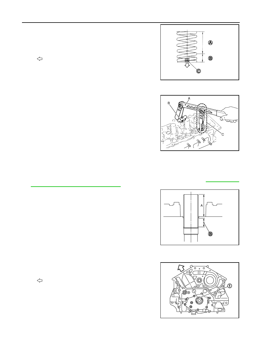
• Install narrow pitch end to cylinder head side (valve spring
seat side).
7.
Install valve spring retainer.
8.
Install valve collet.
• Compress valve spring with the valve spring compressor [SST:
KV10116200 (J-26336-A)] (A), the attachment [SST:
KV10115900 (J-26336-20)] (C) and the adapter [SST:
KV10116200 (
—
)] (B). Install valve collet with a magnet
hand.
CAUTION:
When working, take care not to damage valve lifter holes.
• Tap valve stem edge lightly with plastic hammer after installa-
tion to check its installed condition.
9.
Install spark plug tube.
• Press-fit spark plug tube as per the following:
a.
Remove old locking sealant adhering to cylinder head mounting hole.
b.
Apply sealant to area within approximately 12 mm (0.47 in) from edge of spark plug tube press-fit side.
Use Genuine high strength thread locking sealant or an equivalent. Refer to
mended Chemical Products and Sealants"
c.
Using drift, press-fit spark plug tube so that its height (A) is as
specified in the figure.
CAUTION:
• When press-fitting, take care not to deform spark plug
tube.
• After press-fitting, wipe out liquid gasket protruding onto
cylinder-head upper face.
10. Install new cylinder head gaskets.
11. Turn crankshaft until No. 1 piston is set at TDC.
• Crankshaft key should line up with the bank 1 cylinder center
line as shown in the figure.
A
: Wide pitch
B
: Narrow pitch
C
: Paint mark
: Cylinder head side
Paint mark color
: Yellowish green
JPBIA0179ZZ
JPBIA0180ZZ
B
: High strength thread locking sealant application area
Standard press-fit height:
: 37.7 - 38.7 mm (1.484 - 1.524 in)
1
: Crankshaft key
: Bank 1 side
JPBIA0181ZZ
JPBIA0174ZZ
CYLINDER HEAD
EM-113
< UNIT DISASSEMBLY AND ASSEMBLY >
[VQ35HR]
C
D
E
F
G
H
I
J
K
L
M
A
EM
N
P
O
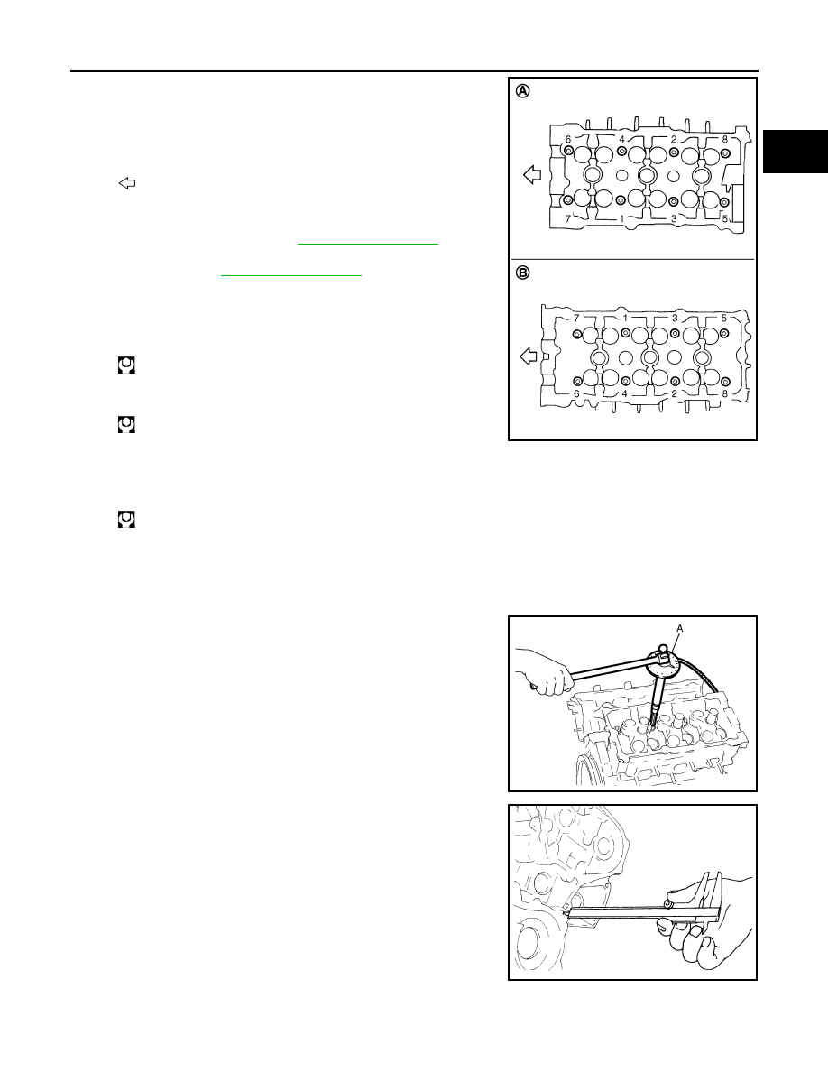
12. Install cylinder head follow the steps below to tighten cylinder
head bolts in numerical order as shown in the figure with cylin-
der head bolts wrench (commercial service tool).
CAUTION:
• If cylinder head bolts re-used, check their outer diameters
before installation. Refer to
.
• Before installing cylinder head, inspect cylinder head dis-
tortion. Refer to
.
a.
Apply new engine oil to threads and seat surfaces of cylinder
head bolts.
b.
Tighten all cylinder head bolts.
c.
Completely loosen all cylinder head bolts.
CAUTION:
In step “c”, loosen bolts in reverse order of that indicated in the figure.
d.
Tighten all cylinder head bolts.
e.
Tighten all cylinder head bolts (clockwise).
CAUTION:
Check the tightening angle by using the angle wrench [SST:
KV10112100 (BT8653-A)] (A). Never make judgment by
visual inspection.
• Check tightening angle indicated on the angle wrench indica-
tor plate.
f.
Tighten all cylinder head bolts again (clockwise).
13. After installing cylinder head, measure distance between front
end faces of cylinder block and cylinder head (bank 1 and bank
2).
• If measured value is out of the standard, reinstall cylinder
head.
14. Install valve lifter.
• Install it in the original position.
A
: Bank 1
B
: Bank 2
: Engine front
: 105 N·m (11 kg-m, 77 ft-lb)
: 0 N·m (0 kg-m, 0 ft-lb)
: 40.0 N·m (4.1 kg-m, 30 ft-lb)
JPBIA0172ZZ
Angle tightening: 95 degrees
Angle tightening: 95 degrees
JPBIA0175ZZ
Standard
: 14.1 - 14.9 mm (0.555 - 0.587 in)
EMQ0662D
EM-114
< UNIT DISASSEMBLY AND ASSEMBLY >
[VQ35HR]
CYLINDER HEAD
15. Install spark plug with spark plug wrench (commercial service tool).
16. Install in the reverse order of removal after this step.
Inspection
INFOID:0000000005245175
INSPECTION AFTER REMOVAL
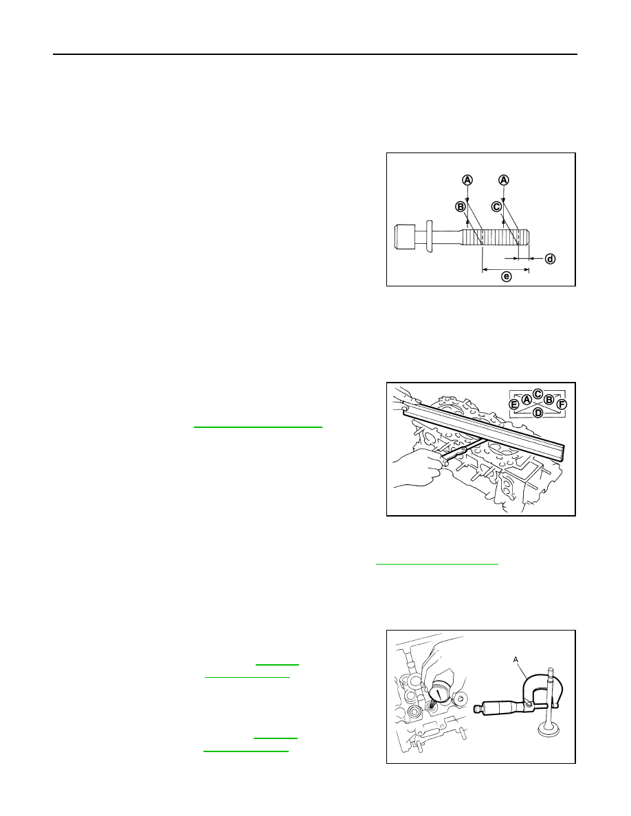
Cylinder Head Bolts Outer Diameter
• Cylinder head bolts are tightened by plastic zone tightening
method. Whenever the size difference between (C) and (B)
exceeds the limit, replace them with new one.
• If reduction of outer diameter appears in a position other than (B),
use it as (B) point.
Cylinder Head Distortion
NOTE:
When performing this inspection, cylinder block distortion should be also checking.
1.
Using a scraper, wipe out oil, scale, gasket, sealant and carbon deposits from surface of cylinder head.
CAUTION:
Never allow gasket fragments to enter engine oil or engine coolant passages.
2.
At each of several locations on bottom surface of cylinder head,
measure the distortion in six directions (A, B, C, D, E, and F).
• If it exceeds the limit, replace cylinder head.
INSPECTION AFTER DISASSEMBLY
Valve Dimensions
• Check the dimensions of each valve. For the dimensions, refer to
.
• If dimensions are out of the standard, replace valve and check valve seat contact. Refer to "VALVE SEAT
CONTACT".
Valve Guide Clearance
Valve Stem Diameter
• Measure the diameter of valve stem with micrometer (A).
Valve Guide Inner Diameter
• Measure the inner diameter of valve guide with bore gauge.
Valve Guide Clearance
• (Valve guide clearance) = (Valve guide inner diameter) – (Valve stem diameter)
Limit [(C) - (B)]
: 0.18 mm (0.0071 in)
A
: Measuring point
e
: 48 mm (1.89 in)
d
: 11 mm (0.43 in)
JPBIA0173ZZ
Limit
: Refer to
.
JPBIA0176ZZ
Standard
: Refer to
.
(Intake and exhaust)
Standard
: Refer to
.
(Intake and exhaust)
JPBIA0183ZZ
CYLINDER HEAD
EM-115
< UNIT DISASSEMBLY AND ASSEMBLY >
[VQ35HR]
C
D
E
F
G
H
I
J
K
L
M
A
EM
N
P
O
• If the calculated value exceeds the limit, replace valve and/or valve guide. When valve guide must be
replaced, refer to
EM-107, "Disassembly and Assembly"
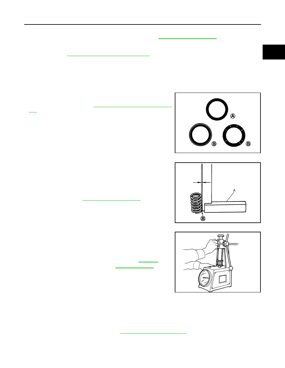
Valve Seat Contact
• After confirming that the dimensions of valve guides and valves are within the specifications, perform this
procedure.
• Apply prussian blue (or white lead) onto contacting surface of valve seat to check the condition of the valve
contact on the surface.
• Check if the contact area band is continuous all around the circumference.
• If not, grind to adjust valve fitting and check again. If the contacting
surface still has “NG” (B) conditions even after the recheck,
replace valve seat. Refer to
EM-107, "Disassembly and Assem-
Valve Spring Squareness
• Set a try square (A) along the side of valve spring and rotate
spring. Measure the maximum clearance between the top of spring
and try square.
• If it exceeds the limit, replace valve spring.
Valve Spring Dimensions and Valve Spring Pressure Load
• Check the valve spring pressure at specified spring height.
• If the installation load or load with valve open is out of the stan-
dard, replace valve spring.
INSPECTION AFTER INSTALLATION
Inspection for Leakage
The following are procedures for checking fluids leakage, lubricates leakage and exhaust gases leakage.
• Before starting engine, check oil/fluid levels including engine coolant and engine oil. If less than required
quantity, fill to the specified level. Refer to
MA-12, "Fluids and Lubricants"
.
• Use procedure below to check for fuel leakage.
- Turn ignition switch “ON” (with engine stopped). With fuel pressure applied to fuel piping, check for fuel leak-
age at connection points.
Valve guide clearance
: Refer to
.
Standard and limit (Intake and exhaust)
A
: OK
JPBIA0187ZZ
B
: Contact
Limit
: Refer to
.
JPBIA0189ZZ
Standard (Intake and exhaust)
: Refer to
.
Free height
Installation height
Installation load
Height during valve open
Load with valve open
SEM113
Нет комментариевНе стесняйтесь поделиться с нами вашим ценным мнением.
Текст