Infiniti FX35, FX50 (S51). Manual — part 530
RADIATOR CORE SUPPORT
DLK-243
< REMOVAL AND INSTALLATION >
C
D
E
F
G
H
I
J
L
M
A
B
DLK
N
O
P
RADIATOR CORE SUPPORT
Exploded View
INFOID:0000000005239724
Removal and Installation
INFOID:0000000005239725
REMOVAL
1.
Use refrigerant collecting equipment to discharge the refrigerant. Refer to
2.
Remove floor under cover. Refer to
EXT-31, "Removal and Installation"
3.
Remove front bumper fascia, front bumper fascia lower, energy absorber and bumper reinforcement.
Refer to
EXT-13, "Removal and Installation"
.
4.
Drain engine coolant from radiator.
• VQ35HR models: Refer to
.
• VK50VE models: Refer to
5.
Remove engine coolant reservoir tank. Refer to
6.
Remove air guide lower (LH/RH).
7.
Remove air guide upper (LH/RH).
8.
Remove front combination lamp (LH/RH). Refer to
.
9.
Disconnect hood lock switch connector from head lamp bracket (RH).
10. Remove mounting bolts and then remove head lamp bracket (LH/RH).
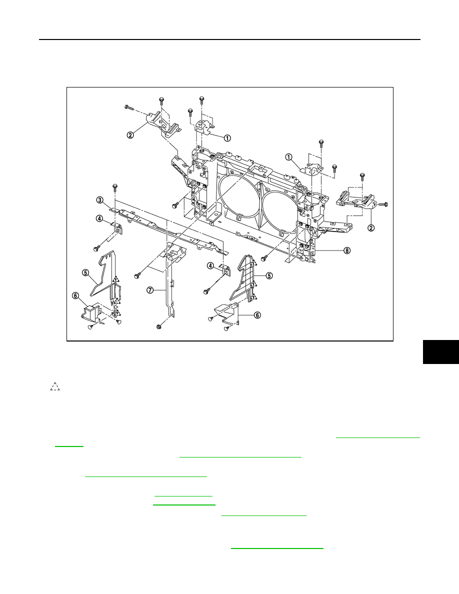
1.
Hood lock bracket (LH/RH)
2.
Head lamp bracket (LH/RH)
3.
Front bumper upper retainer
4.
Front bumper side retainer (LH/RH)
5.
Air guide upper (LH/RH)
6.
Air guide lower (LH/RH)
7.
Hood lock stay
8.
Radiator core support
: Pawl
JMKIA2635ZZ

DLK-244
< REMOVAL AND INSTALLATION >
RADIATOR CORE SUPPORT
11. Remove mounting bolts and then remove hood lock bracket assembly (LH/RH).
12. Remove washer tank and washer tank inlet. Refer to
13. Remove ambient sensor. Refer to
.
14. Remove GAS sensor (with intelligent A/C). Refer to
.
15. Disconnect harness clamp from hood lock stay.
16. Remove mounting bolt and nut, and remove hood lock stay.
17. Remove horn (HIGH/LOW). Refer to
18. Remove ICC sensor integrated unit (with intelligent cruse control model). Refer to
.
19. Remove intelligent key warning buzzer. Refer to
DLK-284, "Removal and Installation"
.
20. Remove power steering oil cooler.
ST-48, "VQ35HR : Exploded View"
ST-49, "VK50VE : Exploded View"
21. Disconnect harness connector of refrigerant pressure sensor. Refer to
22. Remove condenser assembly and condenser pipe assembly. Refer to
23. Disconnect A/T fluid cooler hose (upper/lower) from fan shroud and remove A/T fluid cooler hose (upper/
lower) from radiator.
• VQ35HR, 2WD models: Refer to
.
• VQ35HR, AWD models: Refer to
24. Remove radiator upper hose and lower hose at radiator side.
.
25. Remove radiator.
CO-14, "Removal and Installation"
.
CO-39, "Removal and Installation"
26. Remove crash zone sensor. Refer to
SR-21, "Removal and Installation"
.
27. Disconnect harness connector of cooling fan.
.
28. Disconnect all harness clip from radiator core support assembly.
29. Remove mounting bolts, and then remove radiator core support assembly.
CAUTION:
Operate with two workers, because of its heavy weight.
30. Remove the following parts after removing radiator core support assembly.
• Cooling fan (LH/RH)
- VQ35HR models: Refer to
.
• Front bumper side retainer (LH/RH)
INSTALLATION
Install in the reverse order of removal.
CAUTION:
• After installation, replenish the following parts.
- Refrigerant: Refer to
HA-25, "Collection and Charge"
(VK50VE models).
- Engine coolant: Refer to
(VK50VE models).
- A/T fluid: Refer to
(VQ35HR models) or
(VK50VE models).
- Power steering oil: Refer to
• After installation, adjust the following parts.
- ICC sensor integrated unit (with intelligent cruse control model): Refer to
SERVICE WHEN REPLACING CONTROL UNIT (ICC SENSOR INTEGRATED UNIT) : Special Repair
Requirement"
.
- Front combination lamp: Refer to
EXL-224, "Aiming Adjustment Procedure"
- Perform camera image calibration. Refer to
FRONT FENDER
DLK-245
< REMOVAL AND INSTALLATION >
C
D
E
F
G
H
I
J
L
M
A
B
DLK
N
O
P
FRONT FENDER
Exploded View
INFOID:0000000005239726
Removal and Installation
INFOID:0000000005239727
CAUTION:
Use protective tape or shop cloth to protect from damage during removal and installation.
REMOVAL
1.
Remove clips of hood seal assembly (side) on font fender.
2.
Remove fillet molding. Refer to
EXT-32, "Removal and Installation"
3.
Remove fender protector. Refer to
EXT-25, "FENDER PROTECTOR : Removal and Installation"
4.
Remove front bumper fascia. Refer to
EXT-13, "Removal and Installation"
.
5.
Remove center mud guard. Refer to
EXT-29, "Removal and Installation"
6.
Remove front combination lamp. Refer to
EXL-228, "Removal and Installation"
.
7.
Remove front fender cover.
8.
Remove mounting bolts and remove front fender.
CAUTION:
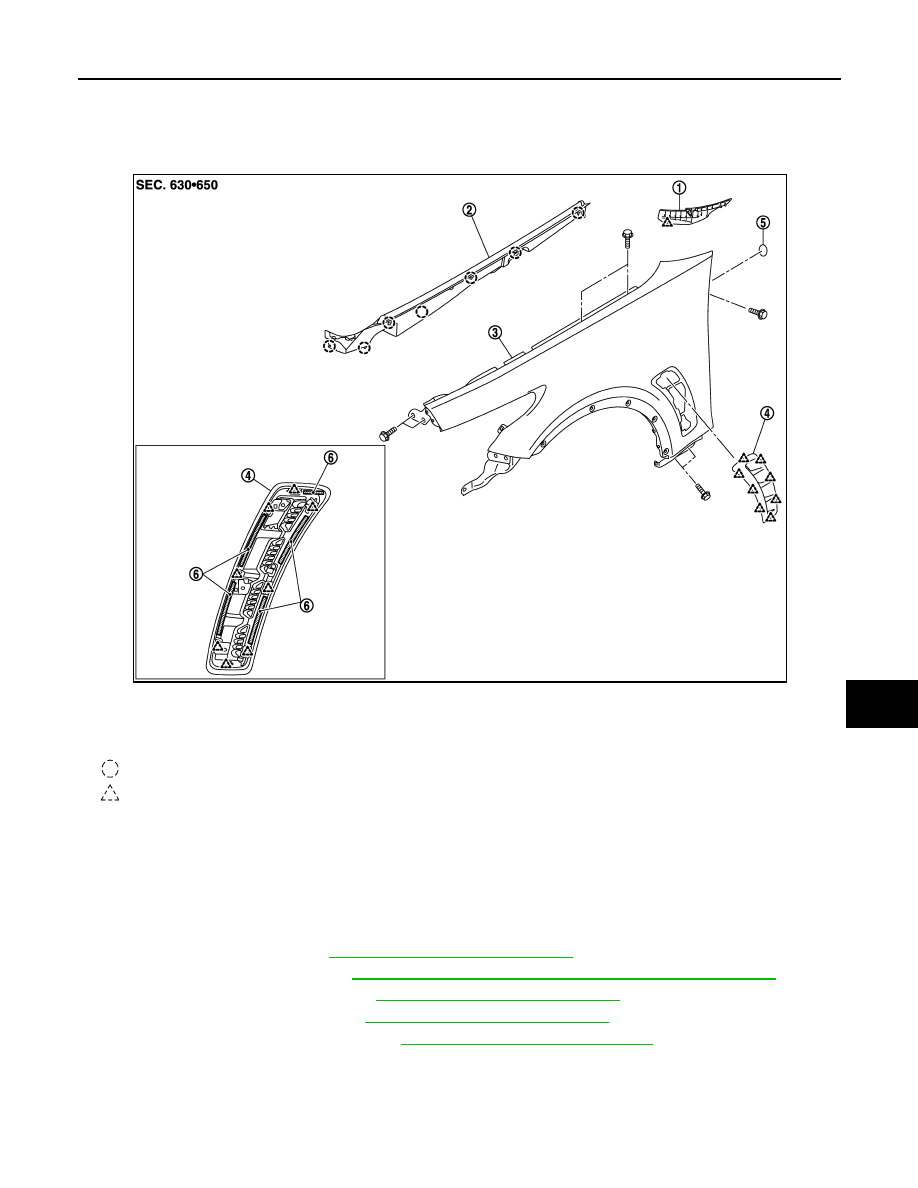
1.
Front fender cover
2.
Hood seal assembly (side)
3.
Front fender
4.
Front fender duct assembly
5.
Seal
6.
Double-faced adhesive tape
(t: 0.8 mm, 0.031 in)
: Clip
: Pawl
JMKIA2636ZZ
DLK-246
< REMOVAL AND INSTALLATION >
FRONT FENDER
A viscous urethane foam is installed on the back surface of front fender. When removing the front
fender, be careful to not deform the front fender while performing the procedure and removing the
viscous urethane foam a little at a time.
INSTALLATION
Install in the reverse order of removal.
CAUTION:
• After installation, apply the touch-up paint (the body color) onto the head of front fender mounting
bolts.
• After installation, adjust the following part.
- Hood assembly: Refer to
DLK-238, "HOOD ASSEMBLY : Adjustment"
.
- Front door: Refer to
DLK-249, "DOOR ASSEMBLY : Adjustment"
- Front combination lamp: Refer to
EXL-224, "Aiming Adjustment Procedure"
- Perform camera image calibration. Refer to
AV-462, "CALIBRATING CAMERA IMAGE (AROUND
VIEW MONITOR) : Work Procedure"
Disassembly and Assembly
INFOID:0000000005239728
1.
Remove fender protector (front). Refer to
EXT-25, "FENDER PROTECTOR : Removal and Installation"
.
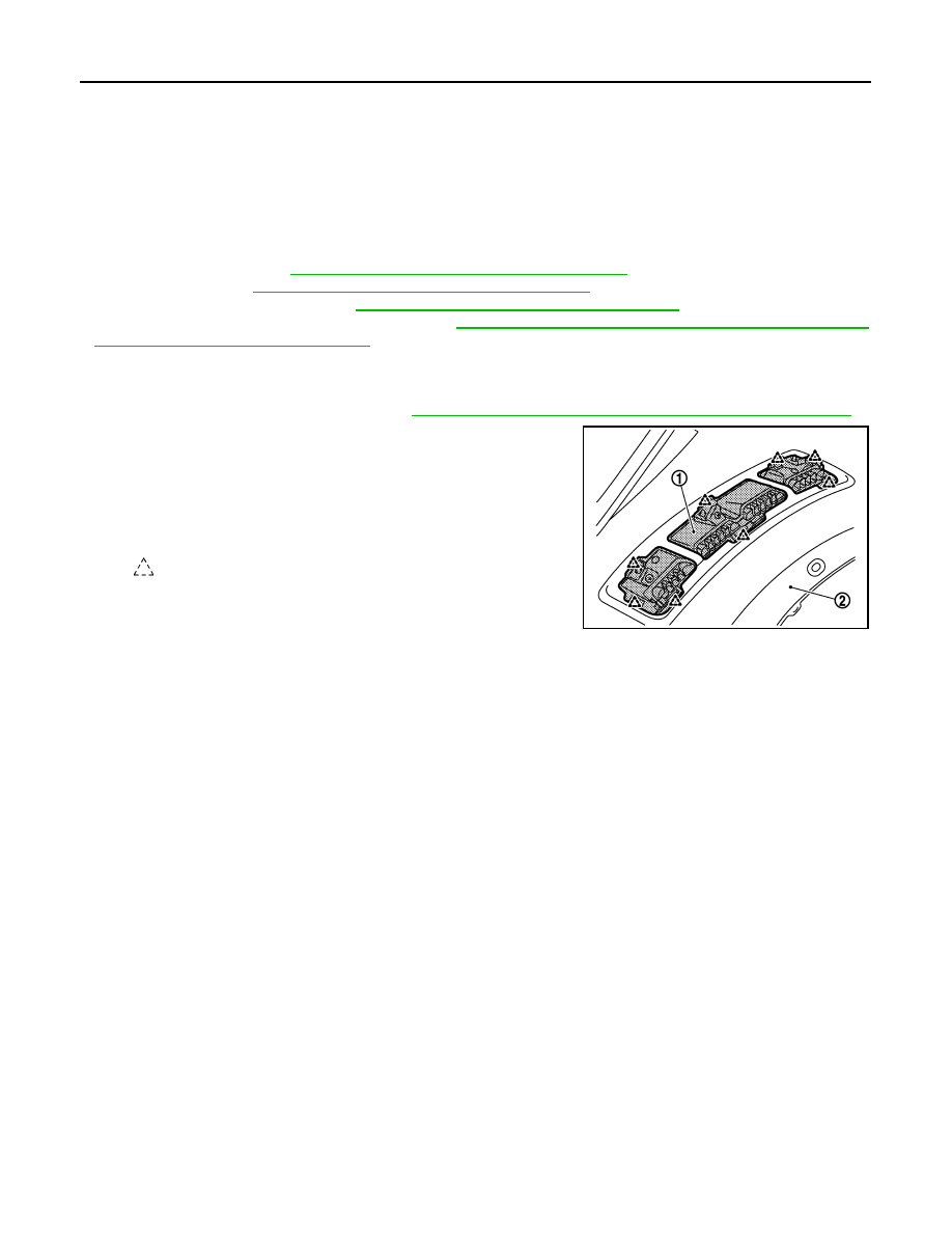
2.
Disengage pawls of front fender duct (1) assembly from front
fender (2) to remove.
CAUTION:
When removing front fender duct assembly, peel off the
double-faced adhesive tape at a time, and carefully to
remove it.
: Pawl
JMKIA2637ZZ
Нет комментариевНе стесняйтесь поделиться с нами вашим ценным мнением.
Текст