Infiniti FX35, FX50 (S51). Manual — part 531
FRONT DOOR
DLK-247
< REMOVAL AND INSTALLATION >
C
D
E
F
G
H
I
J
L
M
A
B
DLK
N
O
P
FRONT DOOR
DOOR ASSEMBLY
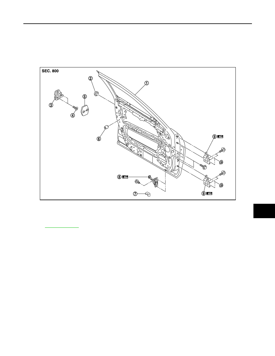
DOOR ASSEMBLY : Exploded View
INFOID:0000000005239729
REMOVAL
ADJUSTMENT
1.
Front door panel
2.
Grommet
3.
Door striker
4.
TORX bolt
5.
Door striker cover
6.
Bumper rubber
7.
Door check link cover
8.
Door check link
9.
Door hinge (upper/lower)
Refer to
JMKIA2639ZZ
DLK-248
< REMOVAL AND INSTALLATION >
FRONT DOOR
DOOR ASSEMBLY : Removal and Installation
INFOID:0000000005239730
CAUTION:
• Operate with two workers, because of its heavy weight.
• Use protective tape or shop cloth to protect from damage during removal and installation.
REMOVAL
1.
Remove mounting bolts of door check link on the vehicle.
2.
Disconnect front door harness connector.
3.
Remove door hinge mounting nuts (door side), and then remove front door assembly.
INSTALLATION
Install in the reverse order of removal.
CAUTION:
• Apply anticorrosive agent onto the mounting surface.
• Check door hinge rotating part for poor lubrication. If necessary, apply body grease.
• After installation, check door open/close, lock/unlock operation.
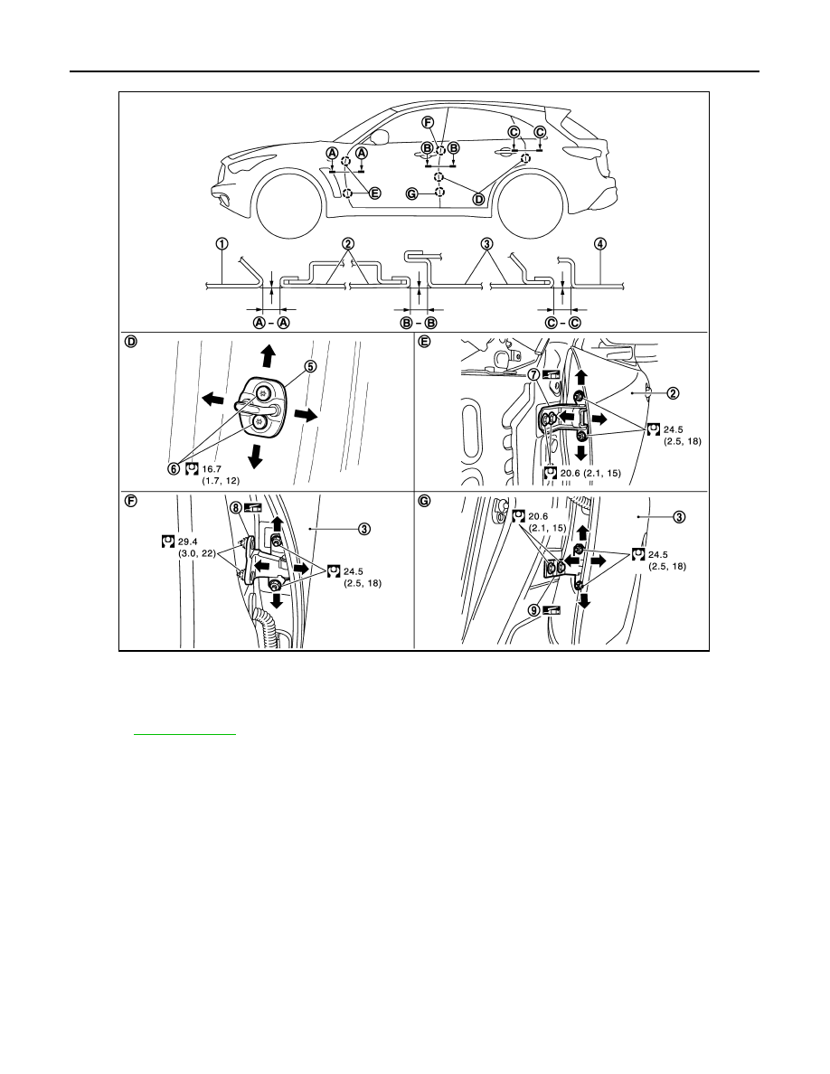
1.
Front fender
2.
Front door
3.
Rear door
4.
Body side outer
5.
Door striker
6.
TORX bolt
7.
Front door hinge (upper/lower)
8.
Rear door hinge (upper)
9.
Rear door hinge (lower)
Refer to
for symbols in the figure.
JMKIA2640GB

FRONT DOOR
DLK-249
< REMOVAL AND INSTALLATION >
C
D
E
F
G
H
I
J
L
M
A
B
DLK
N
O
P
• After installation, perform the fitting adjustment. Refer to
DLK-249, "DOOR ASSEMBLY : Adjust-
• After installation, apply touch-up paint (the body color) onto the head of door hinge mounting bolts
and nuts.
DOOR ASSEMBLY : Adjustment
INFOID:0000000005239731
Check the clearance and surface height between front door and each part by seeing and touching.
If the clearance and surface height are out of specification, adjust them according to the procedures shown
below.
Unit: mm (in)
1.
Remove front fender. Refer to
DLK-245, "Removal and Installation"
.
2.
Loosen door hinge mounting nuts on door side.
3.
Adjust the surface height of front door according to the fitting standard dimension.
4.
Temporarily tighten door hinge mounting nuts on door side.
5.
Loosen door hinge mounting bolts on body side.
6.
Raise front door at rear end to adjust clearance of the front door according to the fitting standard dimen-
sion.
7.
Tighten each bolts and nuts to the specified torque.
CAUTION:
• Apply anticorrosive agent onto the mounting surface.
• Check door hinge rotating part for poor lubrication. If necessary, apply body grease.
• After installation, check door open/close, lock/unlock operation.
• After installation, apply touch-up paint (the body color) onto the head of door hinge mounting
bolts and nuts.
8.
Install front fender. Refer to
DLK-245, "Removal and Installation"
.
DOOR STRIKER ADJUSTMENT
Adjust door striker so that it becomes parallel with door lock insertion direction.
DOOR STRIKER
Portion
Clearance
Surface height
Front fender – Front door
A – A
3.0 – 5.0 (0.118 – 0.197)
−
1.0 – 1.0 (
−
0.039 – 0.039)
Front door – Rear door
B – B
3.0 – 5.0 (0.118 – 0.197)
−
1.0 – 1.0 (
−
0.039 – 0.039)
DLK-250
< REMOVAL AND INSTALLATION >
FRONT DOOR
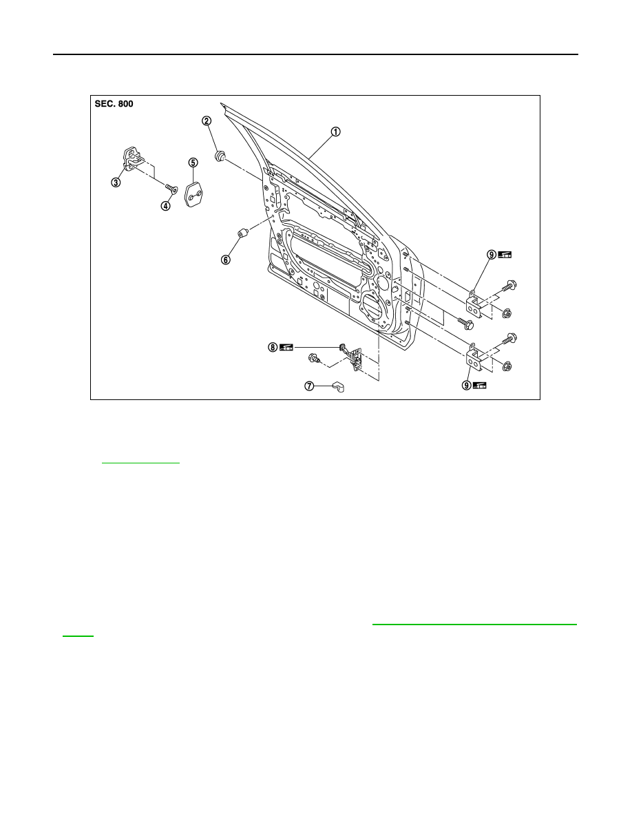
DOOR STRIKER : Exploded View
INFOID:0000000005239732
DOOR STRIKER : Removal and Installation
INFOID:0000000005239733
REMOVAL
1.
Remove door striker cover.
2.
Remove TORX bolts, and then remove door striker.
INSTALLATION
Install in the reverse order of removal.
CAUTION:
• Apply genuine high strength locking sealant or equivalent onto TORX bolts.
• After installation, check door open/close, lock/unlock operation.
• After installation, perform the fitting adjustment. Refer to
DLK-249, "DOOR ASSEMBLY : Adjust-
DOOR HINGE
1.
Front door panel
2.
Grommet
3.
Door striker
4.
TORX bolt
5.
Door striker cover
6.
Bumper rubber
7.
Door check link cover
8.
Door check link
9.
Door hinge (upper/lower)
Refer to
for symbols in the figure.
JMKIA2639ZZ
Нет комментариевНе стесняйтесь поделиться с нами вашим ценным мнением.
Текст